
Related Manuals for Body Solid GLPH2100


Summary of Contents for Body Solid GLPH2100
- Page 1 BODY-SOLID,Inc. 1900 S. Des Plaines Ave. Forest Park, IL 60130 USA Phone:(708)427-3555 Fax:(708)427-3556 www.bodysolid.com GLPH2100.3 OWNER'S MANUAL...
- Page 2 GLPH2100 ASSEMBLY INSTRUCTIONS TABLE OF CONTENTS General Instructions ------------------------------------------------------- 2 Training Tips and Safety Information ----------------------------------3 Inspection and Maintenance Schedule-------------------------------- 4 Hardware Illustration ------------------------------------------------------- 5-6 Parts Illustration---------------------------------------------------------------7-8 Assembly ( Step 1)----------------------------------------------------------9-10 Assembly ( Step 2)----------------------------------------------------------11-12 Assembly ( Step 3)----------------------------------------------------------13-14 Assembly ( Step 4)-----------------------------------------------------------15-16 Assembly (...
- Page 3 GLPH2100 ASSEMBLY INSTRUCTIONS GENERAL INSTRUCTIONS Thank you for purchasing the Body-Solid LPH2100. At Body-solid, our goal is to ensure customer satisfaction. If you have any questions about these instructions or have any problems with assembly or parts for this machine, please call our Customer Service Department at 1-800-5563- 113.
- Page 4 GLPH2100 ASSEMBLY INSTRUCTIONS TRAINING TIPS AND SAFETY INFORMATION Before starting any exercise program, it is recommended that you consult your physician and get a complete physical examination. There is a risk assumed by individuals who use this type of equipment. To minimize risk, follow the rules below.
- Page 5 GLPH2100 ASSEMBLY INSTRUCTIONS INSPECTIONS AND MAINTENANCE SCHEDULE There is a risk assumed by individuals who use this type of equipment. To minimize risk, follow the rules below. ‧ Inspect equipment daily, ensuring that all nuts, bolts and screws are fully tightened.
- Page 6 G LPH2100 ASSEMBLY INSTRUCTIONS HARDWARE ILLUSTRATION Qty . A1. 1/2"X3 1/4" HEX HEAD BOLT ------------------------------------------------------ [4PCS] A2. 1/2"X3" HEX HEAD BOLT ------------------------------------------------------------ [6PCS] A3. 1/2"X5" HEX HEAD BOLT ------------------------------------------------------------ [2PCS] A4. 1/2"X3 1/2" HEX HEAD BOLT ------------------------------------------------------ [4PCS] A5. 1/2"X2 3/4" HEX HEAD BOLT ------------------------------------------------------ [4PCS] ------------------------------------------------------------ [4PCS] A6.
- Page 7 D10 . -------------------------------------------------- [1PCS] 50X75X2.5T END CAP(9211-084) ----------------------------------------------- [2PCS] D11. 36 RUBBER DONUT (9310-033) D12. 38X325 RUBBER PAD (9310-042) ------------------------------------------------ [1PCS] D13. 1" ROUND END CAP (9260-021) ----------------------------------------------- [4PCS] ------------------------------------------------ [1PCS] 50X50X1.8T END CAP (9211-087) D14. Page GLPH2100.3-092012...
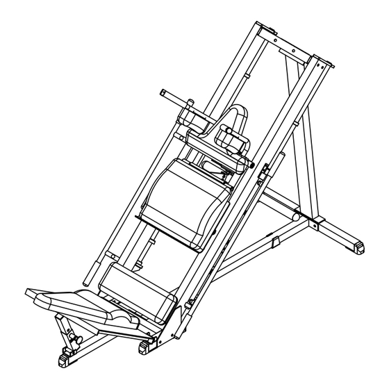
- Page 8 G LPH2100 ASSEMBLY INSTRUCTIONS PARTS ILLUSTRATION E[1PCS] A[1PCS]Upright Framer Rear Base Frame B[1PCS]Middle Base Frame C1[1PCS]Press Back Pad Frame D[1PCS]Front Base Frame F[1PCS]Left Side Frame G[1PCS]Right Side Frame H4[1PCS] J2 [1PCS] Carriage Leg Press Plate Page GLPH2100.3-092012...
- Page 9 GLPH2100 ASSEMBLY INSTRUCTIONS PARTS ILLUSTRATION I2[1PCS] R [1PCS] Weight Post Q [1PCS] Left Shoulder Right Shoulder Frame Frame L [1PCS] Left Safety K [1PCS] Right Safety T [1PCS] S [1PCS] O [1PCS] N [1PCS] M [1PCS] Right Pad Left Pad...
- Page 10 Frame and (A) - Upright Frame to (B) - Middle Base Frame 3. Attach (O) - Top Frame to (A) - Upright Frame 4. Attach (F) - Left Side Frame and (G) - Right Side Frame to (D) - Front Base Frame and (O) - Top Frame Page GLPH2100.3-092012...
- Page 11 GLPH2100 ASSEMBLY INSTRUCTIONS A3X2 Above show STEP 1 C1X2 assembled and completed C1X2 B1X2 C1X4 A5X4 A1X2 C1X2 D9X2 D7X7 D5X2 B1X2 C1X2 C1X2 B1X2 A2X4 C1X4 C1X4 B1X4 C1X2 A2X2 GLPH2100.3-092012 Page 10...
- Page 12 GLPH2100 ASSEMBLY INSTRUCTIONS ASSEMBLY- STEP 2 **Note : Do Not fully tighten frame bolts and nuts until after completing Step 2 The following Parts and Hardware will be needed to complete Step 2 Parts Description Hardware Description Part Part Description...
- Page 13 GLPH2100 ASSEMBLY INSTRUCTIONS Above show STEP assembled and completed 5/16"X5/16" SCREW x2 M10 WASHER Ø19 AAX2 M10X30L ROUND BOLT D1X2 5/16"X5/16" SCREW x2 D2X4 M10 WASHER Ø19 5/16"X5/16" SCREW X2 M10 NYLON LOCK NUT TOOL Ø3/4" × 410L shaft D11X2 3/8"NYLON LOCK NUT...
- Page 14 GLPH2100 ASSEMBLY INSTRUCTIONS ASSEMBLY- STEP 3 **Note : Do Not fully tighten frame bolts and nuts until after completing Step 3 The following Parts and Hardware will be needed to complete Step 3 Parts Description Hardware Description Part Part Description...
- Page 15 GLPH2100 ASSEMBLY INSTRUCTIONS Above show STEP assemble and completed B3X4 C3X4 C3X4 A12X4 D8X4 D13X4 GLPH2100.3-092012 Page...
- Page 16 GLPH2100 ASSEMBLY INSTRUCTIONS ASSEMBLY- STEP 4 **Note : Do Not fully tighten frame bolts and nuts until after completing Step 4 The following Parts and Hardware will be needed to complete Step 4 Parts Description Hardware Description Part Part Description...
- Page 17 GLPH2100 ASSEMBLY INSTRUCTIONS ASSEMBLE-STEP 4 C6X2 A1X2 A11X2 A6X4 C1X2 C2X4 C2X4 B2X4 D6X2 B1X2 THRER IS A RISK ASSUMED BY INDIVIDUALS WHO USE THIS TYPE OF EQUIPMENT . TO MINIMIZE RISK , YOU MUST FOLLOW THESE RULES : 1. Inspect equipment before each workout . Checke that all nuts , bolts , screws and pop pins are in place and fully tightened .
- Page 18 GLPH2100 ASSEMBLY INSTRUCTIONS ASSEMBLY- STEP 5 **Note : Do Not fully tighten frame bolts and nuts until after completing Step 5 The following Parts and Hardware will be needed to complete Step 5 Parts Description Hardware Description Part Part Description...
- Page 19 GLPH2100 ASSEMBLY INSTRUCTIONS ASSEMBLE-STEP 5 C4X2 A7X2 C3X2 A9X8 C4X8 C5X8 A13X4 Page GLPH2100.3-092012...
- Page 20 GLPH2100 ASSEMBLY INSTRUCTIONS ASSEMBLY- STEP 6 **Note : Do Not fully tighten frame bolts and nuts until after completing Step 6 The following Parts and Hardware will be needed to complete Step 6 Parts Description Hardware Description Part Part Description...
- Page 21 GLPH2100 ASSEMBLY INSTRUCTIONS Above show STEP assembled and completed C3X2 A8X2 C4X2 GLPH2100.3-092012 Page 20...
- Page 22 GLPH2100 ASSEMBLY INSTRUCTIONS ASSEMBLY- STEP 7 **Note : Do Not fully tighten frame bolts and nuts until after completing Step 7 The following Parts and Hardware will be needed to complete Step 7 Hardware Description Parts Description Qty Part Part Description Qty Part Part Description 1/2"X3 1/2"...
- Page 23 GLPH2100 ASSEMBLY INSTRUCTIONS Above show STEP assembled and completed C3X4 C4X4 A9X4 B1X4 C1X4 C1X4 A4X4 GLPH2100.3-092012 Page 22...
Need help?
Do you have a question about the GLPH2100 and is the answer not in the manual?
Questions and answers