Table of Contents
Advertisement
Body-Solid
®
Table of Contents
Total Body Workout DVD . . . . . . . . . . . . . p. 2
Reference Drawings . . . . . . . . . . . . . . . . . p. 3
Safety Instructions . . . . . . . . . . . . . . . . . . p. 4
Before You Begin . . . . . . . . . . . . . . . . . . . p. 5
Dimensions . . . . . . . . . . . . . . . . . . . . . . . . p. 6
Safety Guidelines . . . . . . . . . . . . . . . . . . . p. 7
Preparations . . . . . . . . . . . . . . . . . . . . . . . p. 8
Assembly Instructions . . . . . . . . . . . . p. 9-27
Cable Installations . . . . . . . . . . . . . . p. 28-37
Shroud Installation . . . . . . . . . . . . . . p. 40-41
Cable Adjustments . . . . . . . . . . . . . . p. 38-39
Adjustments . . . . . . . . . . . . . . . . . . . p. 42-45
Maintenance Schedule . . . . . . . . . . .p. 48-49
Nutrition . . . . . . . . . . . . . . . . . . . . . . . . . p. 52
Exercise Prescription . . . . . . . . . . . . . . . p. 53
Training Tips . . . . . . . . . . . . . . . . . . . . . . p. 54
Common Training Mistakes . . . . . . . . . . p. 55
Setting Up Your Personal Program . . . . p. 56
Determine Your Training Method . . . . . . p. 57
Exercise Tips . . . . . . . . . . . . . . . . . . . . . . p. 58
Anatomy Chart . . . . . . . . . . . . . . . . . . . . p. 59
Fitness Goals . . . . . . . . . . . . . . . . . . . . . p. 60
Exercise Logs . . . . . . . . . . . . . . . . . . p. 61-63
Stretching: Warm-Up / Cool-Down . p. 65-69
Workout/Exercises . . . . . . . . . . . . . . p. 70-75
Signs of Overtraining . . . . . . . . . . . . . . . p. 76
Weight Ratios . . . . . . . . . . . . . . . . . . . . . p. 77
Obtaining Service . . . . . . . . . . . . . . . . . . p. 79
Mainframe Parts List . . . . . . . . . . . . p. 80-81
Hardware Parts List . . . . . . . . . . . . . p. 82-85
Hardware Diagrams . . . . . . . . . . . . . p. 86-88
Exploded View Diagram . . . . . . . . . . p. 89-90
A s s e m b l y
I n s t r u c t i o n s
&
O W N E R 'S
M A N U A L
Advertisement
Table of Contents

Related Manuals for Body Solid G6B


Summary of Contents for Body Solid G6B
-
Page 1: Table Of Contents
Body-Solid ® Table of Contents Total Body Workout DVD ... . . p. 2 Reference Drawings ....p. 3 Safety Instructions . -
Page 2: Total Body Workout Dvd
T o t a l B o d y Follow the lead of international fitness presenter Geoff Bagshaw as he guides you step by step through a total health and conditioning program. Includes thorough explanations and demonstrations of over 50 exercises targeting all major muscle groups. -
Page 3: Reference Drawings
G 6 B R e f e r e n c e D r a w i n g s... -
Page 4: Safety Instructions
Assemble and operate the G6B on a solid, level • surface. Locate the unit a few feet from the walls or furniture to provide easy access. -
Page 5: Before You Begin
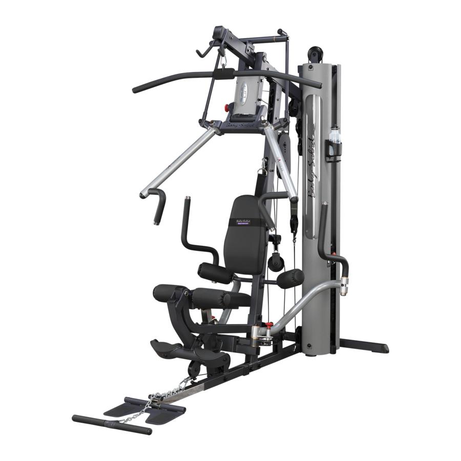
B e f o r e Thank you for purchasing the G6B. This gym is part of the Body-Solid line of quality strength training machines, which let you target specific muscle groups to achieve better muscle tone and overall body conditioning. -
Page 6: Dimensions
The usage space is: width 7’ X length 10’ 4” (The usage space is the overall space needed for operation.) The usage space needed for the G6B could be more, depending on the user, allow enough room for the Low Row Station. -
Page 7: Safety Guidelines
S a f e t y Successful resistance training programs have one prominent feature in common...safety. Resistance training has some inherent dangers, as do all physical activities. The chance of injury can be greatly reduced or completely removed by using correct lifting techniques, proper breathing, maintaining equipment in good working condition, and by wearing the appropriate clothing. -
Page 8: Preparations
CAUTION: To set up this unit, you will need assistance. Do not attempt assembly by yourself. You must review and follow the instructions in this Owner’s Manual. If you do not assemble and use the G6B according to these guidelines, you could void the Body-Solid warranty. -
Page 9: Assembly Instructions
A s s e m b l y Assembly of the G6B takes professional installers about 3 hours to complete. If this is the first time you have assembled this type of equipment, plan on significantly more time. Professional installers are highly recommended! However, if you acquire the appropriate tools, obtain assistance, and follow the assembly steps sequentially, the process will take time, but is fairly easy. - Page 10 S T E P Be careful to assemble all components in the sequence they are presented. NOTE: Finger tighten all hardware in this step. Do Not wrench tighten until end of step 3. Attach Frame Leveler (10) to Main Base Frame (A) as shown. Insert two Weight Stack Shims (11) to Main Base Frame (A) as shown.
- Page 11 S T E P...
- Page 12 S T E P Be careful to assemble all components in the sequence they are presented. NOTE: Finger tighten all hardware in this step. Do Not wrench tighten until end of step 3. Attach Angled Support Frame (D) to Main Base Frame (A) using: Two 40 (1/2”...
- Page 13 S T E P...
- Page 14 S T E P Be careful to assemble all components in the sequence they are presented. NOTE: At this point you must make sure that the gym is level, stable and in the right location. Place two Weight Stack Risers (36) and two Rubber Donuts (14) onto Main Base Frame (A) as shown.
- Page 15 S T E P...
- Page 16 S T E P Be careful to assemble all components in the sequence they are presented. Attach two Convex End Caps (2) to the top of Seated Press Arm Support (H). Attach Seated Press Arm Support (H) to Top Frame (E) using Shaft (33), and tighten Allen Screws (34).
- Page 17 S T E P...
- Page 18 S T E P Be careful to assemble all components in the sequence they are presented. Attach Pec Dec Frame (N) to Angled Support Frame (D) in the bottom two holes as shown using: One 42 (1/2” x 3 3/4” hex head bolt)* Two 43 (1/2”...
- Page 19 S T E P...
- Page 20 S T E P Be careful to assemble all components in the sequence they are presented. NOTE: LEG EXTENSION FRAME (V) AND THE SEAT PAD FRAME (W) ARE PRE-ASSEMBLED AS ONE PIECE. Attach Leg Extension Frame (V) to Angled Support Frame (D) using: Two 40 (1/2”...
- Page 21 S T E P REVERSE SIDE DRAWING...
- Page 22 S T E P Be careful to assemble all components in the sequence they are presented. Attach Pulley Platform (AB) to Main Base Frame (A) as shown using: Two 50 (3/8” x 1” hex head bolt) Four 74 (3/8” washer) Two 71 (3/8”...
- Page 23 S T E P...
- Page 24 S T E P Be careful to assemble all components in the sequence they are presented. Attach Right Leg Hold Down (AG) and Left Leg Hold Down (AH) to the Angled Support Frame (D) using: Two 56 (3/8” x 3 1/4” hex head bolt) Four 78 (3/8”...
- Page 25 S T E P...
- Page 26 S T E P Be careful to assemble all components in the sequence they are presented. NOTE: Leave all pulley bolts hand tight until step 15 is completed. Install Pulley (A3) and Pulley (A5) into Seated Press Arm Support (H) using for each pulley: One 54 (3/8”...
- Page 27 S T E P...
-
Page 28: Cable Installations
S T E P Be careful to assemble all components in the sequence they are presented. Ball Stop End Note: Leave all pulley bolts hand tight until step 15 is completed. Begin at the high pulley station. Route the metal ball end of the High Pulley Cable (85) up and through the opening where Pulley (A1) will be installed. - Page 29 Diagram 1 Cable Installation Start here at high pulley station by inserting the metal ball end here. Diagram 2 Pulley Installation Lat Pulldown Cable S T E P...
- Page 30 S T E P Be careful to assemble all components in the sequence they are presented. Ball Stop End Note: Leave all pulley bolts hand tight until step 15 is completed. Install Pulley (A6) under Cable (85) and into Angled Support Frame (D) using: One 52 (3/8”...
- Page 31 Diagram 1 Cable Installation Lat Pulldown Diagram 2 Pulley Installation Cable S T E P WA R N I N G Selector Rod Top Bolt (103) must be threaded a minumum of 1/2” into the Selector Rod (19), and Jam Nut (104) tightened securely against spring lock washer (105) to ensure proper connection.
- Page 32 S T E P Be careful to assemble all components in the sequence they are presented. Small Ball Stop End Note: Leave all pulley bolts hand tight until step 15 is completed. Insert either end of Low Pulley Cable (86) into the opening in Angled Support Frame (D), above Back Pad (BB), and pull entire length of Cable (86) through.
- Page 33 S T E P Diagram 1 Cable Installation Low Pulley Cable Start here at the Ab-Crunch station by inserting either end here. Diagram 2 Pulley Installation...
- Page 34 S T E P Be careful to assemble all components in the sequence they are presented. Small Ball Stop End Stamped Eye End NOTE: Leave all pulley bolts hand tight until step 15 Route Cable (86) up and through the bottom of 45 Degree Double Pulley Holder (CB). Install Pulley (B5) using: One 51 (3/8”...
- Page 35 S T E P Diagram 1 Cable Installation Low Pulley Cable Short Cable Short Cable 87 Diagram Diagram 2 Pulley Installation...
- Page 36 S T E P Be careful to assemble all components in the sequence they are presented. Stamped Eye End NOTE: Leave all pulley bolts hand tight until step 15 Bolt Pec Dec Cable (88) to Left Pec Dec Cam (P) as shown in diagram 1 using: One 50 (3/8”...
- Page 37 Diagram 1 Cable Installation Pec Dec Cable Start routing cable here by bolting cable to Left Pec Dec Cam (P). Diagram 3 Pulley Installation Diagram 2 Cable Installation S T E P Pec Dec Cable...
-
Page 38: Cable Adjustments
Cable(s) are sloppy and there is no resistance from the weight stack for the first few inches of the exercise. There are FIVE areas for cable adjustment on the G6B: A. Selector Rod Top Bolt (103).* B. TWO adjustments in Double Pulley Holder (CA). - Page 39 Turn and loosen Rubber Stop (105) to take up space and tighten cable. WA R N I N G Selector Rod Top Bolt (103) must be threaded a minimum of 1/2” into the Selector Rod (19), and Jam Nut (104) Loosen tightened securely against spring lock washer (105) to ensure proper connection.
-
Page 40: Shroud Installation
S T E P Be careful to assemble all components in the sequence they are presented. SEE NOTE 1 ON PAGE 41: Apply weight stack numbers to weight stack Top Plate (17) and each Weight Stack Plate (38) as shown. SEE NOTE 2 ON PAGE 41: Weight Stack Shroud (DA) is pre-assembled with Shroud Insert (DB). - Page 41 S T E P NOTE 2 This is the top view of the two Weight Stack Shrouds. Note the shape of each shroud for proper placement. 2” flat side 3/4” flat side NOTE 1 Apply weight stack numbers to the Weight Stack Plates (38).
-
Page 42: Adjustments
A d j u s t m e n t s Congratulations! You are done. After assembly, you should check all functions to ensure correct operation. If you experience problems, first recheck the assembly instructions to locate any possible errors made during assembly. If you are unable to correct the problem, call the dealer from whom you purchased the machine or call 1-800-833-1227 for the dealer nearest you. - Page 43 WA R N I N G Pay special attention to the plunger on this Pop Pin (65). Always be sure that the plunger is fully engaged into the hole you select. Also, be sure that the spring in the Pop Pin (65) operates freely.
- Page 44 A d j u s t m e n t s SEAT PAD (AD) ADJUSTMENT Grasp the Seat Pad (AD). Turn the T-Shaped Pop Pin (63) in Leg Extension Frame (W) counter clockwise to unlock it, and then pull the Pop Pin to release the Seat Pad Frame (W). Adjust the Seat Pad (AD) to the desired position.
- Page 45 WA R N I N G Pay special attention to the plunger on this Pop Pin (104). Always be sure that the plunger is fully engaged into the hole you select. Also, be sure that the spring in the Pop Pin (104) operates freely. Failure to do so may result in serious injury.
-
Page 46: Warning, Safety & Maintenance
W a r n i n g , S a f e t y & M a i n t e n a n c e Be sure that all users carefully read and understand all warning, safety and maintenance labels on the machine before each use. - Page 47 Warning Safety and Maintenance of Cables Although Body-Solid provides the highest quality of materials and workmanship in its products, the fact remains that component parts eventually wear out over time and with use. This is particularly true with reference to pliable moving parts such as cables.
- Page 48 Owners Manual. Routine inspection and maintenance is of critical importance to ensure the maximum safety and performance of the G6B. Body-Solid uses the highest quality materials available, but wear is inevitable. Therefore, you must carefully inspect your equipment as outlined in the Maintenance Schedule on the next page.
-
Page 49: Maintenance Schedule
MAINTENANCE SCHEDULE DAILY WEEKLY LATEST DATE ENTRY CABLES: CHECK TENSION, END FITTINGS, AND COATING. CHECK THAT JAM NUTON THE SELECTOR ROD TOP BOLT IS TIGHT. UPHOLSTERY: WIPE DOWN AND DRY CLEAN AND CONDITION. FRAME: WIPE DOWN AND DRY POLISH/WAX CHROME: WIPE DOWN AND DRY POLISH/LUBRICATE NUTS/BOLTS/FASTENERS:... -
Page 50: Phrases, Terms, Tips & Guidelines
& GUIDELINES B E G I N N E R ’ S • Work out at least two times a week. • Include six to eight exercises that train major muscle groups. • Perform two or three sets of at least eight to 12 repetitions. AEROBIC Exercise that primarily uses oxygen to burn fuel at low to moderate levels of intensity. - Page 51 S T A R T I N G If you begin weight training at too high a level, you risk serious injury. You will also develop poor form, which will hinder your efforts and discourage you. Use this as a guideline: if you cannot lift the weight eight times with proper form, the weight is too heavy.
-
Page 52: Nutrition
Good nutrition is a diet in which foods are eaten in proper quantities and with the needed distribution of nutrients to maintain good health. Malnutrition, on the other hand, is the result of a diet in which there is an underconsumption, overconsumption, or unbalanced consumption of nutrients that leads to disease or an increased susceptibility to disease. -
Page 53: Exercise Prescription
EXERCISE PRESCRIPTION Sets Sets are defined as a combination of any number of reps of one exercise. The number of sets used in a workout is directly related to training results. Typically, two to three sets are used by intermediate and advanced lifters to achieve optimum gains in strength. Experts agree that multiple-set systems work best for the development of strength and muscular endurance. -
Page 54: Training Tips
TRAINING TIPS FOR BEGINNER’S A R E Y O U A beginner can be classified as someone who has never touched a weight, may have lifted for a while, but has taken a substantial amount of time off, or has not consistently trained over the last six months. If you happen to fall into any of these categories, pay close attention, because the following information will be detrimental to the start of your training program. -
Page 55: Common Training Mistakes
COMMON TRAINING MISTAKES 1. Lack of Adequate Warm-Up and Inadequate Flexibility A warmed muscle is a more flexible muscle that’s better able to lift heavier weights and work in a full range of motion. Those warmed muscles also greatly reduce your chance of training injuries. 2. -
Page 56: Setting Up Your Personal Program
SETTING UP YOUR PERSONAL PROGRAM It is important to first establish specific and realistic goals. You should determine your long term goal and then set a series of short term goals that will help you attain your long term goal. The most common goals are: If your personal goals involve losing a... -
Page 57: Determine Your Training Method
DETERMINE YOUR TRAINING METHOD Which training method is right for you? There are three basic types of weight training methods: 1. Training for muscular endurance and definition ENDURANCE & DEFINITION 2. Training for strength This training method incorporates 3. Training for power and achieving and maintaining a high muscle mass cardiovascular (heart) rate and helps... -
Page 58: Exercisetips
Listed below are Body-Solid’s picks of the best exercises you can do for each body part. These exercises can be done using free weights, machines and multi-station gyms. Learn to do each exercise in proper form. You can make substitutions in your training and try variations of each using different Body-Solid grips, cable attachments and accessories to slightly change the emphasis of a particular exercise. -
Page 59: Anatomy Chart
ANATOMY CHART FRONT VIEW Neck Omohyoid Sternohyoid Sternocleidomastoid • Trapezius • • • • • • • • • • • • • Serratus Anterior External Oblique • Rectus Abdominis Tendinous Inscriptions Vastus Thighs Medialis Sartorius Pectineus • Adductor Longus Gracilis Tensor Fasciae Latae •... -
Page 60: Fitness Goals
SHORT-TERM GOALS Date Set Goal Reward Date Set Goal Reward Date Set Goal Reward LONG-TERM GOALS Goal Reward! M a k e s e v e r a l c o p i e s o f t h i s p a g e t o k e e p t r a c k o f y o u r g o a l s a n d a c c o m p l i s h m e n t s . Y o u c a n p r i n t m o r e c o p i e s o f t h i s p a g e b y g o i n g t o h t t p : / / w w w . -
Page 61: Exercise Logs
WEIGHT TRAINING EXERCISE LOG... - Page 62 WEIGHT TRAINING EXERCISE LOG...
- Page 63 WEIGHT TRAINING EXERCISE LOG...
-
Page 64: Stretching & Flexibility
STRETCHING & FLEXIBILITY Flexibility is an important component of physical fitness and needs to be addressed in a resistance training program. The two main purposes for stretching are injury prevention and a faster rate of recovery from exercise. Stretching should be performed in both the warm up and cool down phases of a training session. -
Page 65: Stretching: Warm-Up / Cool-Down
UPPER BACK Cross Arm in Front of Chest MUSCLE(S) AFFECTED: la tissimus dorsi and teres major 1. Stand or sit with the right arm slightly flexed (15° to 30°) and adducted across the chest. 2. Grasp the upper arm just above the elbow, placing the left hand on the posterior side of the upper arm. - Page 66 SIDES Side Bend with Straight Arms MUSCLE(S) AFFECTED: external oblique, latissimus dorsi and serratus anterior 1. Stand with feet 14 to 16 inches apart. 2. Interlace the fingers with palms facing each other. 3. Reach upward with straight arms. 4. Keeping arms straight, lean from waist to left side. Do not bend knees.
- Page 67 POSTERIOR OF THIGH Sitting Toe Touch MUSCLE(S) AFFECTED: hamstrings, spinal erectors and gastrocnemius 1. Sit with the upper body nearly vertical and legs straight. 2. Lean forward from waist and grasp toes with each hand, slightly pull toes towards the upper body, and pull chest towards leg. (If you are very stiff, try to grasp the ankles.) Hold for 10 seconds.
- Page 68 GROIN Straddle (Spread Eagle) MUSCLE(S) AFFECTED: gastrocnemius, hamstrings, spinal erectors, adductors and sartorius 1. Sit with the upper body nearly vertical and legs straight, and spread legs as far as possible. 2. With right hand, grasp toes of right foot and pull on toes slightly, while pulling chest toward right leg.
- Page 69 POSTERIOR OF LOWER LEG Step Stretch MUSCLE(S) AFFECTED: gastrocnemius and soleus; also, achilles tendon 1. Have ready a step or board 3 to 4 inches high. 2. Place balls of both feet on the step or board, 1 inch from its edge. 3.
-
Page 70: Workout/Exercises
Chest Press (Pectorals) 1. Insert pin into weight stack at desire resistance level. 2. Adjust seat pad height so that when seated the horizontal press handles bisect the upper chest (pectoral major) muscles. 3. Seat yourself comfortably on the seat pad with your back straight. 4. - Page 71 Lat Pulldown (Latissimus Dorsi) 1. Insert pin into weight stack at desired resistance level. 2. Attach Lat Bar to high pulley cable. 3. Adjust seat pad so your knees fit comfortably under leg hold-down foam rollers. Sit on seat pad facing into machine. 4.
- Page 72 Standing Cable Curl (Biceps) 1. Insert pin into weight stack at desired resistance level. 2. Attach Low Row Bar to low pulley cable. 3. Take an underhand grasp on the Bar. Stand erect with your feet set at shoulder width, approximately 1 to 2 feet away from pulley.
-
Page 73: Upright Row
Deltoid Raise (Deltoids) 1. Insert pin into weight stack at desired resistance level. 2. Attach Stirrup Handle (optional) to low pulley cable. 3. Take an overhand grasp of the Stirrup Handle with your left hand and your palm facing down. 4. -
Page 74: Standing Leg Curl
Standing Leg Curl (Hamstrings) 1. Insert pin into weight stack at desired resistance level. 2. Stand facing machine and hook your left heel under the bottom roller pad with left knee positioned slightly below the top roller pad. Grasp back pad or seated press handles for stability. - Page 75 Ab Crunch (Abdominals) 1. Insert pin into weight stack at desired resistance level. 2. Attach Triceps Strap to the middle pulley cable. 3. Sit comfortably on seat pad with your back resting against back pad. Grasp the Triceps Strap and place it over your shoulders, keeping your hands planted firmly on your upper chest throughout the entire exercise movement.
-
Page 76: Signs Of Overtraining
S i g n s In the quest for better health and fitness, it is sometimes difficult to quell one’s enthusiasm and take a break from exercise. But if exercise is leaving you more exhausted than energized, you could be suffering from an acute case of overtraining. -
Page 77: Weight Ratios
Lat Pulldown Ab Crunch 100% Leg Curl / Leg Extension Top Plate lbs. 12 8 16 0 16 8 W e i g h t R a t i o s 100% 100% Low Row 100% lbs. lbs. lbs. 1 0 0 16 2 18 0 Vertical Handle... - Page 78 BUILD THE ULTIMATE FITNESS CENTER with Rubber Flooring #RF46 45°Hyperextension Vertical Knee Raise / Dip / 40" Wide 3-Tier Machine Push-Up / Chin Machine Dumbbell Rack #WHYP45 #VKR82 #WDR363 Accessories Elliptical Machine Olympic Weight Tree #WT46 Strength Training Time Clock Covered Pentathlon Treadmill #STT45...
-
Page 79: Obtaining Service
O b t a i n i n g Please retain this Owner’s Manual for future reference. When ordering parts you must use the part number and description from this Owner’s Manual. Use only Body-Solid replacement parts when servicing this machine. Failure to do so will void your warranty and could result in personal injury. -
Page 80: Mainframe Parts List
G 6 B M a i n f r a m e KEY# QTY PART# G6BMBF-A G6BRBF-B G6BRVF-C G6BASF-D G6BTF-E G6BGR-F G6BTWSF-G G6BSPAS-H G6BBAB-J G6BBAS-JA G6BBAF-JB G6BBARA-JC G6BBALA-JD G6BBARJ-LE G6BBALJ-LF G6BBARP-JG G6BBALP-JH G6BPAH-K G6BLS-KA G6BRS-KB G6BLPA-L G6BLPAP-LA G6BRPA-M G6BRPAP-MA G6BPDF-N G6BLPDC-P G6BLPDA-Q G6BLPDH-R... - Page 81 KEY# QTY PART# G6BLEP-AA G6BSP-AD G6BBP-BB P u l l e y KEY# QTY PART# G6BDPH-CA G6B45DPH-CB G6B90DPH-CC G6BSPH-CD S h r o u d KEY# QTY PART# G6BWSS-DA G6BSI-DB G6BBWSS-DC Part numbers are required when ordering parts. P a d s L i s t DESCRIPTION LEG EXTENSION PADS...
-
Page 82: Hardware Parts List
G 6 B KEY# QTY PART# JSNAP3 JCEC2X2 JCEC1X2 JCEC2X3 JPREC2.5 JFC2X2 JSC.75 JNW3 JREC2 JFL22 JWSS22 JRP1.5X1.5 JRP1.5X3 JRD2.5 JEC1.5X3 JGT3.75X5.5 JTP10 JFR4X8 JSR25 JREC1X1.5 JPP4.25 JPP3.5 JOW1X1..37 JREC1 JCEC2X2 JEC1X2 JPREC JNB2X2 JS.75X7 JAS.31X.31 JS1X9.75 JRAB.37X.62 JHEX.5X.75PTB JSP10 JFRB JHEX.5X3.25PTB JHEX.5X3.5PTB... - Page 83 G 6 B H a r d w a r e KEY# QTY PART# JCC1X1.37 JS.5X3 JOB.5 JRAHB.31X.5 JHEX.37X1PTB JHEX.37X1.75PTB JHEX.37X2.75PTB JHEX.37X3PTB JHEX.37X7.25PTB JCB.37X2.75PTB JHEX.37X3.25PTB JHEX.37X2.5PTB JSHA.37X2FTB JRA.37X.62FTB JHEX.31X1.5FTB JAHB.31X.75FTB JHEX.31X1.75PTB JTSPP3 JS16 JTSPP7 JFAHB.31X.5 JFP6 JFP6.75 JNLN.5 JNLN.37 JWFLT.5 JWFLT.37 JSLW.37 JWFLT.31...
- Page 84 G 6 B H a r d w a r e KEY# QTY PART# JRAHB.37X.62 JRAHB.12X.37 JFPP3.75 JWSPL JCC1X1.37 JAS.19X.19 JRS2.5 JJN.37 JCES.5X.75 JAB.125X.31 JAB.37X.875FTB JSRTB.5X2FTB JJN.5 JSLW.5 JFPP4.75 JFG1.5X26 JACN.19 JHSA JFG1.5X8.5 JFG1.5X18 JLBP JFG1.5X14 JNB2X2X6 JSB.75X1.37 JBB.62X1 JBB1X1.75 JBB1X1.75 JBB.5X.87 JSB1X1.37...
- Page 85 C a b l e KEY# QTY PART# JHPC5060 JLPC5150 JSC747 JPDC2025 A c c e s s o r i e s KEY# QTY PART# G6BAS G6BACH G6BWBB G6BWBS G6BWBH G6BLRB G6BLB Part numbers are required when ordering parts. L i s t DESCRIPTION HIGH PULLEY CABLE 5060mm 16’...
-
Page 86: Hardware Diagrams
G 6 B ( s h o w n KEY #40 HEX HEAD BOLT 1/2” X 3 1/4” PARTIAL THREAD QTY. 12 KEY #41 HEX HEAD BOLT 1/2” X 3 1/2” PARTIAL THREAD QTY. 1 KEY #42 HEX HEAD BOLT 1/2” X 3 3/4” PARTIAL THREAD QTY. 3 KEY #43 HEX HEAD BOLT 1/2”... - Page 87 G 6 B ( s h o w n KEY #55 CARRIAGE BOLT 3/8” X 2 3/4” PARTIAL THREAD QTY. 2 KEY #54 HEX HEAD BOLT 3/8” X 7 1/4” PARTIAL THREAD QTY. 2 KEY #56 HEX HEAD BOLT 3/8” X 3 1/4” PARTIAL THREAD QTY. 2 KEY #53 HEX HEAD BOLT 3/8”...
- Page 88 G 6 B H A R D W A R E ( s h o w n a c t u a l s i z e ) KEY #74 WASHER 3/8” QTY. 48 KEY #70 NYLON LOCK NUT 1/2” QTY.
- Page 89 part J includes: part JA part JB part JC part JD part JE part JF part JG part JH part M includes: part L includes: part MA part LA © Copyright 2003. Body-Solid. All rights reserved. Body-Solid reserves the right to change design and specifications when we feel it will improve the product. Body-Solid machines maintain several patented and patent pending features and designs.
-
Page 90: Exploded View Diagram
E X P L O D E D V I E W D I A G R A M G 6 B...