
Related Manuals for Body Solid GLEG


Summary of Contents for Body Solid GLEG
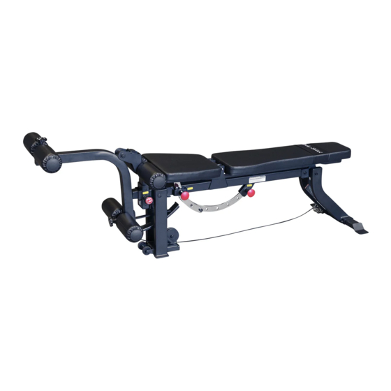
- Page 1 GLEG & A s s e m b l y I n s t r u c t i o n s O W N E R ’ S M A N U A L V. GLEG-20230712...
- Page 2 W a r n i n g , S a f e t y & M a i n t e n a n c e Be sure that all users carefully read and understand all warning, safety and maintenance labels on the machine before each use.
-
Page 3: Table Of Contents
T a b l e o f C o n t e n t s • SAFETY INSTRUCTIONS......PAGE 4 • PREPARATION..........PAGE 5 • PART / HARDWARE LIST....... PAGE 6 • HARDWARE ILLUSTRATION......PAGE 8 • ASSEMBLY INSTRUCTIONS......PAGE 12 • EXPLODED VIEW.......... -
Page 4: Safety Instructions
Si vous avez des etourdissements ou des faiblesses, arretez les exercices immediatement. Antes de comenzar cualquier programma de ejercicios, deberias tener un examen fisico con su doctor. When using exercise equipment, you The GLEG is designed for your enjoyment. By following should always take basic precautions, these precautions and using common sense, you will... -
Page 5: Preparation
P r e p a r a t i o n Thank you for purchasing the GLEG. This Product is part of the Body-Solid line of quality strength training machines, which lets you target specific muscle groups to achieve better muscle tone and overall body conditioning. To maximize your use of the equipment please study this Owner’s Manual thoroughly. Required Tools Assembly Tips The basic tools that you must obtain before assembling Read all “Notes” on each page before beginning each the GLEG include but are not limited to: step. While you may be able to assemble the GLEG using the illustrations only, important safety notes and other tips m Standard Wrench Set are included in the text. -
Page 6: Part / Hardware List
G L E G P a r t s & H a r d w a r e L i s t Part# Description MAIN FRAME FRONT LEG REAR LEG REAR STABILIZER BACK REST ADJUSTMENT BRACKET SEAT ADJUSTMENT BRACKET SEAT FRAME BACK FRAME HEIGHT ADJUSTMENT FRAME FOAM ROLLER BAR... - Page 7 G L E G P a r t s & H a r d w a r e L i s t Part# Description TWIST LOCK POP PIN POP PIN RUBBER BUMPER METAL BUSHING, ø19xø15xø12x16mm FOAM ROLLER PLASTIC END CAP THUMB SCREW, M8x125mm PLASTIC SLEEVE SEAT PAD BACK PAD PAD WRAP...
-
Page 8: Hardware Illustration
G L E G H a r d w a r e I l l u s t r a t i o n Part #1 HEX HEAD BOLT M10x185mm QTY. - Page 9 G L E G H a r d w a r e I l l u s t r a t i o n Part #6 HEX HEAD BOLT M10x20mm QTY.
- Page 10 G L E G H a r d w a r e I l l u s t r a t i o n Part #11 PHILLIPS HEAD SCREW ST4.8x9.5mm QTY.
- Page 11 G L E G H a r d w a r e I l l u s t r a t i o n Part #16 WASHER M8 QTY.
-
Page 12: Assembly Instructions
S T E P Be careful to assemble all components in the sequence they are presented. NOTE: Wrench tighten ALL hardware at the end of STEP 1C. Some components may be pre-assembled. Nylon lock nuts will not fully screw onto bolts, they must be wrench tighten to fully go on. - Page 13 S T E P Above shows Step 1 assembled and completed.
- Page 14 S T E P Be careful to assemble all components in the sequence they are presented. NOTE: Wrench tighten ALL hardware at the end of STEP 2C. Some components may be pre-assembled. Nylon lock nuts will not fully screw onto bolts, they must be wrench tighten to fully go on.
- Page 15 S T E P Above shows Step 2 assembled and completed.
- Page 16 S T E P Be careful to assemble all components in the sequence they are presented. NOTE: Some components may be pre-assembled. Nylon lock nuts will not fully screw onto bolts, they must be wrench tighten to fully go on. 3A. Insert Foam Roller Bar (K) into Height Adjustment Frame (J).
- Page 17 S T E P Above shows Step 3 assembled and completed.
- Page 18 N o t e s...
-
Page 19: Exploded View
G L E G E x p l o d e d V i e w... -
Page 20: Contact Page
GLEG PLEASE WRITE YOUR SERIAL NUMBER IN THE BOXES BELOW 018495-��-��-����-���� S/N # 1900 S. Des Plaines Ave. Forest Park, IL 60130 Phone:(708)427-3555 Fax:(708)427-3556 Hours: M-F 8:30 - 5:00 CST www.bodysolid.com Copyright 2009. Body-Solid. All rights reserved. Body-Solid reserves the right to change design and specifications when we feel it will improve the product.
Need help?
Do you have a question about the GLEG and is the answer not in the manual?
Questions and answers