
Related Manuals for Body Solid GLA378


Summary of Contents for Body Solid GLA378
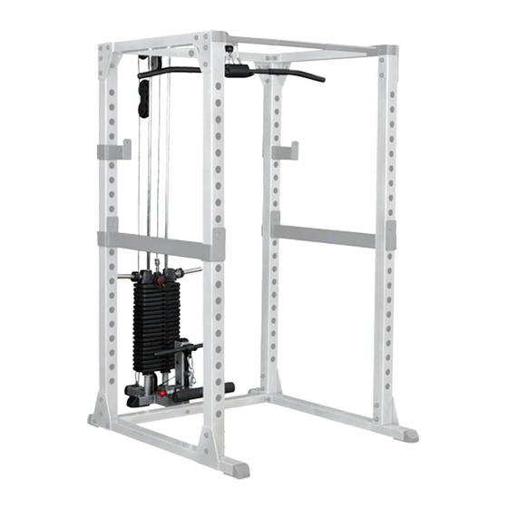
- Page 1 ® GLA378 ® & A s s e m b l y I n s t r u c t i o n s O W N E R ’ S M A N U A L v. 042009...
- Page 2 If you skip ahead, you may learn later that you have to disassemble components and that you may have damaged the equipment. m Assemble and operate the GLA378 on a solid, level surface. Locate the unit a few feet from the walls or furniture to provide easy access.
-
Page 3: Unpacking The Equipment
B e f o r e Y o u B e g i n Thank you for purchasing the GLA378. This gym is part of the Body-Solid line of quality strength training machines, which lets you target specific muscle groups to achieve better muscle tone and overall body conditioning. -
Page 4: Installation Requirements
CAUTION: To set up this unit, you will need assistance. Do not attempt assembly by yourself. You must review and follow the instructions in this Owner’s Manual. If you do not assemble and use the GLA378 according to these guidelines, you could void the Body-Solid warranty. -
Page 5: Assembly Tips
A s s e m b l y I n s t r u c t i o n s Assembly of the GLA378 takes professional installers about 1 hour to complete. If this is the first time you have assembled this type of equipment, plan on significantly more time. - Page 6 S T E P Be careful to assemble all components in the sequence they are presented. NOTE: Finger tighten all hardware in this step unless otherwise noted. Some components may be pre-assembled Connect Bottom Frame (20) to Rear Bottom Frame (7) using: GPR378 Two 13 (12*100mm hex head bolt)
- Page 7 S T E P Above shows STEP1 assembled and completed Above shows Step 1 assembled and completed. Above shows STEP1 assembled and completed...
- Page 8 S T E P Be careful to assemble all components in the sequence they are presented. NOTE: Finger tighten all hardware in this step unless otherwise noted. Some components may be pre-assembled Place 3/4” Rubber Donuts (49) onto the welded risers on Bottom Frame (20). Slide Guide Rods (27) through 3/4”...
- Page 9 S T E P Above shows STEP2 assembled and completed Above shows Step 2 assembled and completed. Above shows STEP2 assembled and completed...
- Page 10 S T E P Be careful to assemble all components in the sequence they are presented. NOTE: Finger tighten all hardware in this step unless otherwise noted. Some components may be pre-assembled Insert End Cap (53) and Round End Caps (54) into Foot Brace (25). Attach Grip Tapes (58) to Foot Brace (25).
- Page 11 S T E P S T E P S T E P S T E P Above shows STEP3 assembled Above shows STEP3 assembled Above shows STEP3 assembled and completed and completed and completed Above shows Step 3 assembled and completed. Above shows STEP3 assembled and completed...
- Page 12 S T E P Be careful to assemble all components in the sequence they are presented. NOTE: Finger tighten all hardware in this step unless otherwise noted. Some components may be pre-assembled Insert Rubber Grips (39) onto Lat Pull Down Bar (21). Connect Snap Link (47) onto the Snap Link Loop on Lat Pull Down Bar (21).
- Page 13 S T E P 52-B 52-A Above shows Step 4 assembled and completed. 52-C 52-D 52-H 52-G 52-E W A R N I N G Diagram 1A 52-F (at least) 1/2” WARNING...
- Page 14 H a r d w a r e L i s t Part# Description 12*105mm HEX HEAD BOLT PARTIAL THREAD 12*100mm HEX HEAD BOLT PARTIAL THREAD 12mm NYLON NUT 12mm WASHER 75*50mm END CAP 75*50mm FOOT CAPS LOW ROW BAR TOP FRAME BOTTOM FRAME LAT PULL DOWN BAR...
- Page 15 H a r d w a r e L i s t Part# Description RUBBER COVER RUBBER COVER WEIGHT STACK PIN T-SHAPED POP PIN CABLE END SHAFT 10*16.5mm PULLEY SPACER SNAP LINK 10*26mm PULLEY SPACER 19*19.5mm RUBBER DONUT SHAFT COVER 25*19.5mm RUBBER DONUT PULLEY 50*50mm END CAP...
- Page 16 H a r d w a r e ( T o S c a l e )
- Page 17 H a r d w a r e ( T o S c a l e )
- Page 18 H a r d w a r e ( T o S c a l e )
- Page 19 E X P L O D E D V I E W D I A G R A M G L A 3 7 8...
- Page 20 ® 1900 S. Des Plaines Ave. Forest Park, Il 60130 1 (800) 556-3113 Hours: M-F 8:30 - 5:00 www.bodysolid.com Copyright 2009. Body-Solid. All rights reserved. Body-Solid reserves the right to change design and specifications when we feel it will improve the product. Body-Solid machines maintain several patented and patent pending features and designs.
Need help?
Do you have a question about the GLA378 and is the answer not in the manual?
Questions and answers