Table of Contents
Advertisement
Quick Links
GDR-44
A s s e m b l y
O W N E R ' S
by
by
VERSION 1010
&
®
Table of Contents
Dimensions. . . . . . . . . . . . . . . . . . . . . . . . . . . p. 2
Reference Drawings. . . . . . . . . . . . . . . . . . . p. 3
Important Safety Instructions. . . . . . . . . . . p. 4
®
Before You Begin. . . . . . . . . . . . . . . . . . . . . . p. 5
Preparations. . . . . . . . . . . . . . . . . . . . . . . . . . p. 6
Assembly Instructions. . . . . . . . . . . . . . . . . p. 7-11
Mainframe Parts List. . . . . . . . . . . . . . . . . . . p. 12
Hardware List. . . . . . . . . . . . . . . . . . . . . . . . . p. 13
Hardware (To Scale). . . . . . . . . . . . . . . . . . . p. 14
Exploded View Diagram. . . . . . . . . . . . . . . . p. 15
I n s t r u c t i o n s
M A N U A L
by
GDR-44
®
v. 110410
Advertisement
Table of Contents

Related Manuals for Body Solid GDR-44


Summary of Contents for Body Solid GDR-44
-
Page 1: Table Of Contents
® GDR-44 GDR-44 ® Table of Contents Dimensions......p. 2 Reference Drawings....p. 3 Important Safety Instructions. -
Page 2: Dimensions
D i m e n s i o n s The room layout diagram below will help you decide the best placement for your GDR-44. The room layout diagram below will help you decide the best placement for your GDR-44. -
Page 3: Reference Drawings
G D R - 4 4 Reference Drawings G D R - 4 4 Reference Drawings use the following diagrams to become more accustomed with your GDR-44 and its applications. G D R - 4 4 Reference Drawings G D R - 4 4 Reference... -
Page 4: Important Safety Instructions
Such attachments might cause injuries. damaged the equipment. Wear proper exercise clothing and shoes for your Assemble and operate the GDR-44 on a solid, level workout, no loose clothing. surface. Locate the unit a few feet from the walls or furniture to provide easy access. -
Page 5: Before You Begin
Body-Solid customer service, M-F 8:30am-5:00pm CST, at one of the following: The GDR-44 is designed for your enjoyment. By fol- lowing these precautions and using common sense, Toll Free: (800) 556-3113 you will have many safe and pleasurable hours of... -
Page 6: Preparations
To set up this unit, you will need assistance. Do not attempt assembly by yourself. You must review and follow the instructions in this Owner’s Manual. If you do not assemble and use the GDR-44 according to these guidelines, you could void the Body-Solid warranty. Installation Requirements CAUTION ! -
Page 7: Assembly Instructions
(in actual size) along with the corresponding component num- While you may be able to assemble the GDR-44 us- bers in the assembly instructions. ing the illustrations only, important safety notes and other tips are included in the text. - Page 8 S T E P Be careful to assemble all components in the sequence they are presented. NOTE: Finger tighten all hardware in this step. Insert both Foot Caps (5) into each Base Frame (B). Attach both Rubber Clips (6) onto Cross Bar (A) at the position shown. Connect Base Frame (B) to Cross Bar (A) using: Two 1 (M10x70 hex head bolt) Two 4 (M10 washer)
- Page 9 S T E P S T E P Above shows STEP assembled and completed Above shows STEP Above shows Step 1 assembled and completed. assembled and completed...
- Page 10 S T E P Be careful to assemble all components in the sequence they are presented. NOTE: Wrench tighten all hardware at the end of this step. Connect each Upright Frame (D) to Base Frame (B) as shown using for each assembly: Two 2 (M10x20 hex head bolt) Two 3 (M10 nylon lock nut) Connect Upper Junction (C) to both Upright Frame (D) using:...
- Page 11 S T E P S T E P S T E P Above shows STEP assembled and completed Above shows Step 2 assembled and completed. Above shows STEP assembled and completed...
-
Page 12: Mainframe Parts List
M a i n f r a m e P a r t s L i s t Part# Description CRoSS BAR BASe FRAme UppeR JUnCTIon (8333-005) UpRIGhT FRAme (8323-046) Part numbers are required when ordering parts. -
Page 13: Hardware List
H a r d w a r e L i s t Part# Description heX heAD BoLT m10x70L heX heAD BoLT m10x20L nYLon LoCK nUT WASheR m10x27 FooT CAp (9211-024) RUBBeR CLIp 2” x 2” (9212-010) BoDYSoLID LoGo (9440-027) GeneRAL WARnInG STICKeR (9440-105) mAInTenAnCe LABeL (9440-103) -
Page 14: Hardware (To Scale)
H A R D W A R E (To Scale) H A R D W A R E (To Scale) H a r d w a r e ( T o S c a l e ) Part1# M10x70L Hex Head Bolt Qty.4 H A R D W A R E (To Scale) Part1# M10x70L Hex Head Bolt Qty.4 Part1# M10x70L Hex Head Bolt Qty.4... -
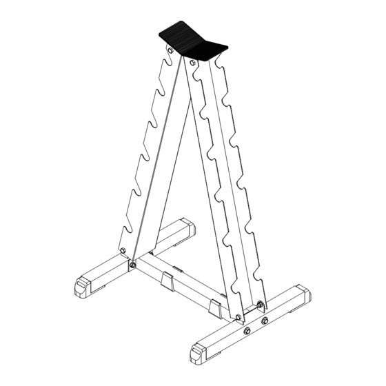
Page 15: Exploded View Diagram
GDR-44 E x p l o d e d V i e w D r a w i n g PAGE 1... - Page 16 ® 1900 S. Des plaines Ave. Forest park, Il 60130 (800) 556-3113 hours: m-F 8:30 - 5:00 www.bodysolid.com Copyright 2010. Body-Solid. All rights reserved. Body-Solid reserves the right to change design and specifications when we feel it will improve the product. Body-Solid machines maintain several patented and patent pending features and designs.
Need help?
Do you have a question about the GDR-44 and is the answer not in the manual?
Questions and answers