Table of Contents
Advertisement
Quick Links
GDR-60
A s s e m b l y
O W N E R ' S
by
by
&
®
Table of Contents
Dimensions. . . . . . . . . . . . . . . . . . . . . . . . . . . p. 2
Reference Drawings. . . . . . . . . . . . . . . . . . . p. 3
Important Safety Instructions. . . . . . . . . . . p. 4
Before You Begin. . . . . . . . . . . . . . . . . . . . . . p. 5
®
Preparations. . . . . . . . . . . . . . . . . . . . . . . . . . p. 6
Assembly Instructions. . . . . . . . . . . . . . . . . p. 7-9
Mainframe Parts List. . . . . . . . . . . . . . . . . . . p. 10
Hardware List. . . . . . . . . . . . . . . . . . . . . . . . . p. 11
Hardware (To Scale). . . . . . . . . . . . . . . . . . . p. 12
Exploded View Diagram. . . . . . . . . . . . . . . . p. 13
Notes. . . . . . . . . . . . . . . . . . . . . . . . . . . . . . . . p. 14-15
I n s t r u c t i o n s
M A N U A L
by
GDR-60
®
v. 110110
Advertisement
Table of Contents

Related Manuals for Body Solid GDR-60


Summary of Contents for Body Solid GDR-60
-
Page 1: Table Of Contents
® GDR-60 GDR-60 ® Table of Contents Dimensions......p. 2 Reference Drawings....p. 3 Important Safety Instructions. -
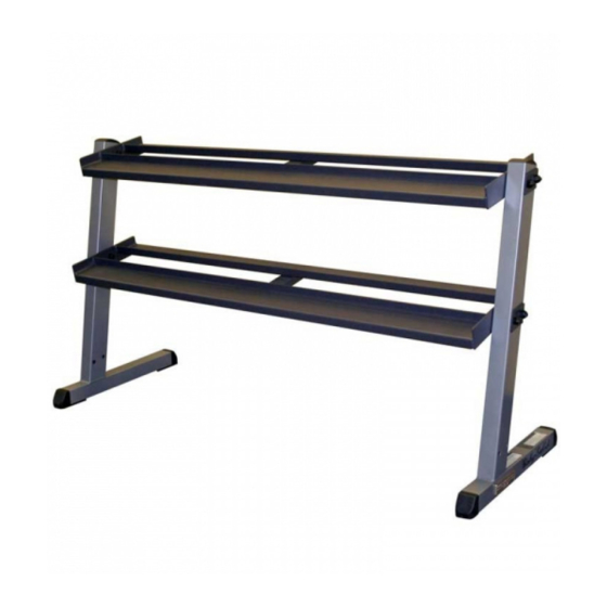
Page 2: Dimensions
The dimensions of the GDR-60 are: Width 2'10" X Length 5'. The ceiling height requirement for the GCAB360 is 2'9". The usage space needed for the GDR-60 could be more, depending on the user. The usage space needed for the GDR-60 could be more, depending on the user. -
Page 3: Reference Drawings
G D R - 6 0 Reference Drawings assembling your GDR-60. Becoming familiar with the unit and the orientation of its components will help ease installation. Please use the following diagrams to become more accustomed with your GDR-60 and its applications. ® ®... -
Page 4: Important Safety Instructions
Such attachments might cause injuries. damaged the equipment. Wear proper exercise clothing and shoes for your Assemble and operate the GDR-60 on a solid, level workout, no loose clothing. surface. Locate the unit a few feet from the walls or furniture to provide easy access. -
Page 5: Before You Begin
Body-Solid customer service, M-F 8:30am-5:00pm CST, at one of the following: The GDR-60 is designed for your enjoyment. By fol- lowing these precautions and using common sense, Toll Free: (800) 556-3113 you will have many safe and pleasurable hours of... -
Page 6: Preparations
To set up this unit, you will need assistance. Do not attempt assembly by yourself. You must review and follow the instructions in this Owner’s Manual. If you do not assemble and use the GDR-60 according to these guidelines, you could void the Body-Solid warranty. Installation Requirements CAUTION ! -
Page 7: Assembly Instructions
(in actual size) along with the corresponding component num- While you may be able to assemble the GDR-60 us- bers in the assembly instructions. ing the illustrations only, important safety notes and other tips are included in the text. - Page 8 Insert End Cap (4) into each Main Base Frame (A). Assemble lower Rack (B) to both Main Base Frame (A) using: Four 1 (M12x75 flat allen head) Two C (plate) Four 2 (M12 nylon lock nut) Assemble upper Rack (B) to both Main Base Frame (A) using: Four 1 (M12x75 flat allen head) Two C (plate) Four 2 (M12 nylon lock nut) Congratulations! The GDR-60 installation is complete.
- Page 9 S T E P S T E P S T E P Above shows Step 1 assembled and completed. Above shows STEP assembled and completed Above shows STEP assembled and completed ...
-
Page 10: Mainframe Parts List
M a i n f r a m e P a r t s L i s t Part# Description MAIN BASE FRAME RACk PLATE 50 x 5T x 75L (8312-168) Part numbers are required when ordering parts. -
Page 11: Hardware List
H a r d w a r e L i s t Part# Description FLAT ALLEN HEAD M12x75 NYLON LOCk NUT FOOT CAP 2” x 2” (9211-024) END CAP 50x75L (9211-084) GENERAL WARNING STICkER (9440-105) BODYSOLID LOGO (9440-027) MAINTENANCE LABEL (9440-103) BODYSOLID PLASTIC PLATE (9440-199) -
Page 12: Hardware (To Scale)
H A R D W A R E (To Scale) H a r d w a r e ( T o S c a l e ) Part#1 M12X75L Round Bolt Qty.8 Part# 1 M12x75 Flat Allen Head Bolt Qty. -
Page 13: Exploded View Diagram
GDR-60 PAGE 1... -
Page 14: Notes
N o t e s... - Page 15 N o t e s...
- Page 16 ® 1900 S. Des Plaines Ave. Forest Park, Il 60130 (800) 556-3113 Hours: M-F 8:30 - 5:00 www.bodysolid.com Copyright 2010. Body-Solid. All rights reserved. Body-Solid reserves the right to change design and specifications when we feel it will improve the product. Body-Solid machines maintain several patented and patent pending features and designs.
Need help?
Do you have a question about the GDR-60 and is the answer not in the manual?
Questions and answers