Advertisement
Quick Links
USER MANUAL
EN
Chapter index
1. Identification data
2. Preliminary warnings
3. Description and characteristics
3.1 Module description
3.2 General characteristics and features
4. Technical specifications
4.1 Inputs
4.2 Outputs
4.3 Connections
4.4 1500 V
insulations
~
4.5 Power supply
4.6 Module case
4.7 Environmental conditions
4.8 Standards
5. Preliminary instructions for use
6. Electrical connections
6.1 Safety measures before use
6.2 USB interface
6.3 Connections
7. Parameters for use
7.1 Setting parameters
7.2 Dip - Switch tables
7.3 Default configuration
8. Decommissioning and disposal
9. Purchase order code
10. Module layout
10.1 Module layout and signalling LEDs
10.2 Block diagram
This document is property of SENECA srl. Duplication and reproduction of its are forbidden (t
Contents of present documentation refers to products and technologies described in it. Though we strive for reach perfection
continually, all technical data contained in this document may be modified or added due to technical and commercial needs; it's
impossible eliminate mismatches and discordances completely. Contents of present documentation is anyhow subjected to
periodical revision. I
f you have any questions
mentioned.
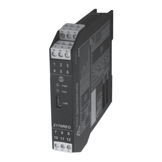
Z170REG
SENECA s.r.l.
Via Austria, 26 – 35127 – PADOVA – ITALY
Tel. +39.049.8705355 – 8705359 Fax. +39.049.8706287
Internet site:
www.seneca.it
Commercial reference:
don't hesitate to contact our structure or to write us to e-mail addresses as above
MI002286-E
Universal converter module
with galvanic insulation
-1
between 2 analog outputs
Page
1
2
2
2
5
5
6
IN, OUT1,OUT2, power
supply are isolated (1500V )
IN, OUT1,OUT2 are:
10
10
Analog and universal
10
Setting by Dip-Switches
Technical assistance:
sales@seneca.it
Z Line
support@seneca.it
hough
partial), if not authorized.
ENGLISH 1/16
~
Advertisement

Related Manuals for Seneca Z Line Z170REG-1


Summary of Contents for Seneca Z Line Z170REG-1
- Page 1 Commercial reference: sales@seneca.it This document is property of SENECA srl. Duplication and reproduction of its are forbidden (t hough partial), if not authorized. Contents of present documentation refers to products and technologies described in it. Though we strive for reach perfection continually, all technical data contained in this document may be modified or added due to technical and commercial needs;...
- Page 2 - It’s possible to power the sensor if input is in current type modality (max17V). - It’s possible to configure by Dip-Switch or by software (available at www.seneca.it) modality: input-type, outputs-type, start / end scale of each selected input and outputs-type - It’s possible to configure by software: input filter, rejection, burn-out, etc..
- Page 3 Errors related to max Accuracy Thermal Linearity error EMI measuring range stability 0.1% 0.01%/°K 0.05% <1% (2) Voltage or current- input type 0.1% 0.01%/°K 0.2°C <1% (2) TC-input type: J, K, E, T, N 0.1% 0.01%/°K 0.5°C <1% (2) TC-input type: R, S TC-input type: B (3) 0.1% 0.01%/°K 1.5°C...
- Page 4 4.4 1500 V INSULATIONS The isolation voltage between: - power supply - analog input OUT-V OUT-V - analog output 1 OUT 2 OUT- OUT- OUT 1 - analog output 2 (figure 1). 1500 V~ Power Supply AC , DC 4.5 POWER SUPPLY 10 –...
- Page 5 6.2 USB INTERFACE The module has a microUSB connector, you can configure it through APP and/or software. Programming tools, manuals, templates, examples, etc. for the product can be downloaded free of charged at www.seneca.it in the Z170REG section. SENECA SENECA...
- Page 6 INPUTS (SENSORS «S» CONNECTION) OUTPUT 1 OUTPUT 2 Active module Passive module 2-wire RTD The module The sensor power the loop power the loop (in mA) (in mA) Voltage 11(+) 7(+) 10(-) 3-wire RTD 11(-) Current (Z170REG active) Voltage mV/TC 4-wire RTD Current (Z170REG passive) With R = 330 W...
- Page 7 7.2 DIP-SWITCH TABLES The module acquires the parameters through Dip-Switches, if the module Dip- Switches are configurated as shown in the following tables 1, 2, 3, 4. For whatever other Dip-Switches configuration, ALL parameters are acquired from memory, regardless of the Dip-Switches configuration. In the following tables: box without circle means Dip-Switch=0 (OFF state);...
- Page 8 Table 3 - START-SCALE VALUES FOR SELECTED INPUT TYPE 6 7 8 Voltage Current TC J TC K TC R TC S TC T 0 mA -200 °C -200 °C 0 °C 0 °C -200 °C 0.5 V 1 mA -100 °C -100 °C 100 °C...
- Page 9 The values of setting parameters configurated by Dip-Switches modality has priority over the values stored in memory EEPROM. If you want change any of the parameters then you can find software and applications in the download area of the website www.seneca.it. MI002286-E ENGLISH 9/16...
- Page 10 8. DECOMMISSIONING AND DISPOSAL Disposal of Electrical & Electronic Equipment (Applicable throughout the European Union and other European countries with separate collections programs). This symbol, found on your product or on its packaging, indicates that this product should not be treated as household waste when you wish to dispose of it.
- Page 11 If there is an «error status» then the module has at least one of the following errors: Tipo di errore Descrizione Tipo di ingresso interessato Input error The amplitude of the acquired input signal is Voltage, current, less than (greater than) the input start scale potentiometer, (end scale) or the TC/RTD sensor is damaged thermocouple,...
- Page 12 Input type Module hardware limits Voltage 0 V; 10.5 V Current 0 mA; 21 mA Potentiometer 0; 100 % Thermocouple If TC J: -210°C; 1200°C. If TC K: -270°C; 1370°C. If TC R: - 50°C;1760°C. If TC S: -50°C;1760°C.If TC T: -270°C; 400°C. If TC B: 0;1820°C.
- Page 13 This page intentionally left blank. 10.2 BLOCK DIAGRAM POWER 19 – 28 V~ 10 – 40 V~ SUPPLY FILTER LIMITER 1 (0-19) LIMITER 2 Block Block meaning (figure 5) FILTER (0-19) 20-levels filter, which an input-acquired signal is applied Analog to Analog Converter LIMITER 1, 2 Signal-amplitude limiters for Output 1, 2 ENGLISH 13/16...
- Page 14 This page intentionally left blank. ENGLISH 14/16 MI002286-E...
- Page 15 This page intentionally left blank. ENGLISH 15/16 MI002286-E...
- Page 16 This page intentionally left blank. ENGLISH 16/16 MI002286-E...
Need help?
Do you have a question about the Z Line Z170REG-1 and is the answer not in the manual?
Questions and answers