Seneca Z-4DI-2AI-2DO Installation Manual
4 digital in - 2 analog in - 2 relay digital out
modbus rtu
Hide thumbs
Also See for Z-4DI-2AI-2DO:
- Installation manual (9 pages) ,
- Installation manual (6 pages) ,
- Installation manual (9 pages)
Table of Contents
Advertisement
Quick Links
Language manual
Product
Description
Contents:
2.2 General features
...
7.2 Software configuration
Manufacturer
Web
Mail
This document is property of SENECA srl. Duplication and reprodution are forbidden, if not authorized. Contents of
the present documentation refers to products and technologies described in it. All technical data contained in the
document may be modified without prior notice Content of this documentation is subject to periodical revision.
INSTALLATION GUIDE
Pag.
2
2
2
4
4
5
6
7
7
Tel. +39.049.8705355 - 8705359 - Fax +39.049.8706287
MI003032-E
4 digital in - 2 analog in - 2 relay digital out
Via Austria, 26 - 35127 - PADOVA - ITALIA
English
Z-4DI-2AI-2DO
Modbus RTU
Seneca s.r.l.
www.seneca.it
support@seneca.it
sales@seneca.it
ENGLISH 1/8
Advertisement
Table of Contents

Related Manuals for Seneca Z-4DI-2AI-2DO


Summary of Contents for Seneca Z-4DI-2AI-2DO
- Page 1 Mail sales@seneca.it This document is property of SENECA srl. Duplication and reprodution are forbidden, if not authorized. Contents of the present documentation refers to products and technologies described in it. All technical data contained in the document may be modified without prior notice Content of this documentation is subject to periodical revision.
-
Page 2: Technical Specifications
No warranty is guaranteed in connection with faults resulting from improper use, from modifications or repairs carried out by Manufacturer-unauthorised personnel on the module, or if the content of this user Manual is not followed. Seneca S.r.l. www.seneca.it Headquarter: Via Germania, 34 - 35127 - Z.I. -
Page 3: Analog Inputs
3.7 Box Dimensions 100 x 35 x 111 mm Box; protection degree Black, PA6, IP20 3.8 Connectors 3.8 Connectors IDC 10 for Seneca bus Connectors Removable terminals, pitch 5,08 mm Mini-B USB 3.9 Standars 3.9 Standards EN 61000-6-4/ 2007 Emission, industrial envinromental... -
Page 4: Preliminary Instructions For Use
4.0 PRELIMINARY INSTRUCTIONS FOR USE The module is designed to be installed on DIN 46277 rail (fig.1) in vertical position. No operation on the module is allowed while it is power on. It is forbidden to install the module near heat-emitting devices It is reccomended that the use and installation operations are performed by an electrical-skilled technician 5.0 INSTALLATION... -
Page 5: Electrical Connections
6.1 Morsetti 6.2 USB 6.2 USB USB port with mini-B plug-in for a easy PC connection. This port allows to use the Easy setup configuration software to configure the module or update firmware (free download from www.seneca.it). mini-B ENGLISH 5/8 MI003032-E... -
Page 6: Table Of Contents
IMPORTANT: the dip-switch SW2 placed at the right of the switch number 8 must be always in position ON! ALWAYS ON Default 7.1 Dip-Switch 6.1 Morsetti 7.2 Easy Setup 7.2 Easy SETUP 7.2 Easy SETUP The configuration software (Easy setup) can be free donwloaded from the website www.seneca.it. MI003032-E ENGLISH 6/8... -
Page 7: Signalling Leds
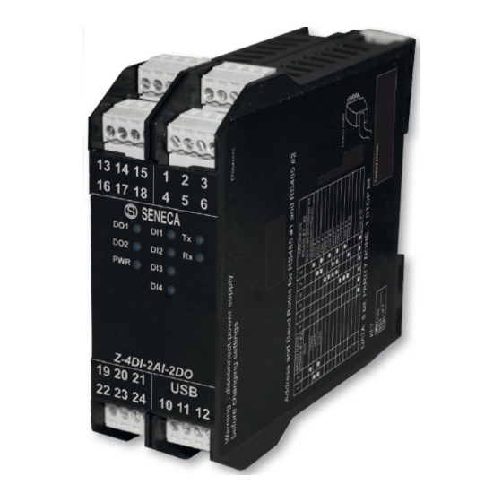
8.0 SIGNALLING LEDs STATE MEANING Blinking The device sends a correct data packet Tx (GREEN) Blinking The device receives a correct data packet (at least one of two buses) Rx (RED) ON / OFF Status of digital input 1, 2, 3, 4 DI1, DI2, DI3, DI4 (REDs) ON / OFF Status of relay output 1, 2... - Page 8 ENGLISH 8/8 MI003032-E...
Need help?
Do you have a question about the Z-4DI-2AI-2DO and is the answer not in the manual?
Questions and answers