Table of Contents
Advertisement
Quick Links
SENECA
S
Z-PC Line
Z-PC Line
Z-PC Line
Z-PC Line
Z-PC Line
Z-PC Line
Z-PC Line
Z-PC Line
EN
EN
EN
EN
Installation
Installation
Manual
Manual
Contents:
- General specifications
- Technical features
- Modbus and CANopen connections
- Installation rules
- Electrical connections
- LEDs signallings
- Default conditions
- Module layout
- Accessories
- Decommissioning and disposal
SENECA s.r.l.
Via Austria, 26 – 35127 – PADOVA – ITALY
Tel. +39.049.8705355 - 8705359 - Fax +39.049.8706287
For manuals and configuration software, please see www.seneca.it
This document is property of SENECA srl. Duplication and reproduction are forbidden, if not authorized.
Contents of the present documentation refers to products and technologies described in it. All technical data
contained in the document may be modified without prior notice. Content of this documentation is subject to
periodical revision.
Advanced Multifunction Control unit
Advanced Multifunction Control unit
IEC 61131 Codesys embedded
IEC 61131 Codesys embedded
Z-TWS5
Z-TWS5
MI003651-E
ENGLISH 1/8
Advertisement
Table of Contents

Subscribe to Our Youtube Channel
Related Manuals for Seneca Z-PC Z-TWS5


Summary of Contents for Seneca Z-PC Z-TWS5
- Page 1 Tel. +39.049.8705355 - 8705359 - Fax +39.049.8706287 For manuals and configuration software, please see www.seneca.it This document is property of SENECA srl. Duplication and reproduction are forbidden, if not authorized. Contents of the present documentation refers to products and technologies described in it. All technical data contained in the document may be modified without prior notice.
- Page 2 1500 V isolation between power supply and other low voltage circuits Easy wiring of power supply and serial communication port through Seneca bus for rail IEC EN 60715. Removable screw terminals with section of 2.5 mm ...
- Page 3 Power supply Supply voltage 10 – 40 V; 19 – 28 V 50 – 60 Hz Power consumption Typical: 4 W @ 24V , Max: 6 W Environmental conditions Temperature -0 – +55°C Humidity 30 – 90% a 40°C not condensing Altitude Fino a 2000 m a.s.l.
- Page 4 MODBUS and CANOPEN connection standards 1) Install the module into the DIN rail. 2) Please use a cable with a suitable length to connect the remote modules. The following table show the cables length. - Bus Length: Modbus network maximum length as a function of the Baud rate. This is the length of the cables which connect the two bus terminators modules.
- Page 5 Electrical Connections Power supply, MODBUS and CAN interface Power Supply and Modbus interface are available by using the bus for the Seneca DIN rail, by the rear IDC10 connector or by Z-PC-DINAL1-35 accessory. Rear IDC10 Connector CAN/RS485 GND Power Supply AC / + The picture shows the meaning of the IDC10 connector pins.
- Page 6 Other Z-TWS5 Ports USB #1 HOST Port The Z-TWS5 has a USB HOST type A connector, that can be used as additional serial port (using a Seneca USB #1 HOST S117P1, for example) or to connect an external USB memory.
- Page 7 Plug-in Connector for Micro SD Card Micro SD card The Z-TWS5 has a slot for micro SD SD card card placed on the side of the case metal Before pushing the SD card in this slot, contacts please be sure that the SD card metal contacts are facing towards left (Please see the figure on side).
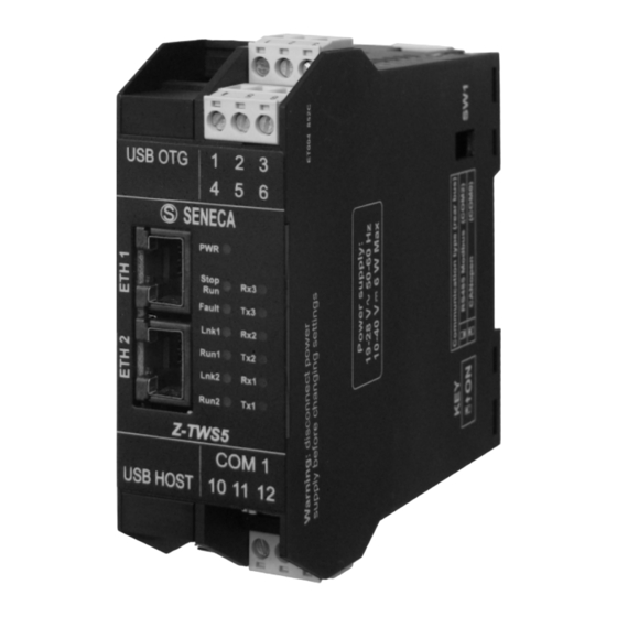
- Page 8 Module layout 100 mm 35 mm 1112 1 2 3 USB OTG 4 5 6 Stop Fault Run1 Lnk1 Run2 Lnk2 Z-TWS5 COM 1 10 11 12 USB HOST Accessories CODE DESCRIPTION Z-PC-DINAL1-35 DIN rail support with screw terminals 1 slot pitch=35 mm Z-PC-DIN1-35 DIN rail support: 1 slot for rear connector pitch=35 mm Z-PC-DIN4-35...
Need help?
Do you have a question about the Z-PC Z-TWS5 and is the answer not in the manual?
Questions and answers