Advertisement
SENECA
S
EN
EN
Installation
Installation
Installation
Installation
Manual
Manual
Manual
Manual
Contents:
- General features
- Technical specifications
- Installation and connections
- Functioning
- Programming
- LEDs signallings
- Countries in which the Z-LINK1 can be
used
SENECA s.r.l.
Via Austria, 26 - 35127 - PADOVA - ITALY
Tel. +39.049.8705355 - 8705359 - Fax +39.049.8706287
For manual and configuration softwares, see www.seneca.it
This document is property of SENECA srl. Duplication and reprodution are forbidden, if not
Contents of the present documentation refers to products and technologies described in it. All technical data
contained in the document may be modified without prior notice Content of this documentation is subject to
periodical revision.
Z-LINK1-LO
Z-LINK1-LO
LoRa radio
communication device
MI004640-E
authorized.
ENGLISH 1/8
Advertisement
Table of Contents

Related Manuals for Seneca Z-LINK1-LO


Summary of Contents for Seneca Z-LINK1-LO
- Page 1 Tel. +39.049.8705355 - 8705359 - Fax +39.049.8706287 For manual and configuration softwares, see www.seneca.it This document is property of SENECA srl. Duplication and reprodution are forbidden, if not authorized. Contents of the present documentation refers to products and technologies described in it. All technical data contained in the document may be modified without prior notice Content of this documentation is subject to periodical revision.
-
Page 2: Technical Specifications
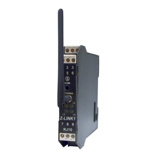
GENERAL FEATURES The Z-LINK1 modules represent a communication systems for data acquisition and transmission in the process control and industrial / civil automation. Based on an UHF modem radio, Z-LINK1 is able to comunicate with Z-PC line modules through ModBUS protocol. - Page 3 20 – 85 % ( without condensing ) -Removable screw terminals:conductors up to 2.5 mm Connections : -RJ10 connector for RS232 serial port -JACK stereo connector for programming -SMA connector for antenna -IDC10 connector for Seneca bus Mounting: For DIN IEC EN 60715 rail Case : PA6, black 100 x 112 x 17,5 mm, 200 g.
- Page 4 As it is illustrated in the next figure: 1) Insert the rear IDC10 connector on a DIN rail free slot (the inserting is univocal since the connectors are polarized). 2) Tighten the locks placed at the sides of the rear IDC10 connector to fix the module.
- Page 5 The electric connections for power supply and RS485 can be made by using either the terminals or the bus for B (-) the Seneca DIN rail. A (+) RS232 serial port for programming only The module has a Jack stereo...
- Page 6 9600 baud - 8N1 (*)Communication parameters from EEPROM (default:38400 baud - 8N1) FUNCTIONING MODALITY OF RADIO MODULE The module radio is internally connected to IDC10 (bus Seneca RS485) and screw terminals (7-8-9) Follow the procedure described in the software Easy setup (@ 9600-8N1)
- Page 7 Missing of a slave device in a network of Z-LINK1 it is possible to observe a timeout message on all slave devices enquired (Z-8TC). connected directly to a Z-LINK1 via local bus) during interrogation by the Modbus master, via bus). If there is the absence of a Modbus slave device (for example, one Z-4AI devices connected directly via bus and a PC as Modbus master (with a Z-LINK1 connected Assume a system consisting of: a network of Z-LINK1 devices with some Modbus slave Z-LINK1...
- Page 8 PROGRAMMING To download the free configuration software Easy setup, see the website www.seneca.it To program the module, use the front connector (COM) with Easy Setup software only and set all communication parameters correctly. In any case, to program the device, refers to Easy Setup software instructions.
Need help?
Do you have a question about the Z-LINK1-LO and is the answer not in the manual?
Questions and answers