Table of Contents
Advertisement
Quick Links
USER MANUAL
EN
Chapter index
5.5 Thermoresistance input
This document is property of SENECA srl. Duplication and reproduction of it are forbidden (though partial), if not authorized.
Contents of present documentation refers to products and technologies described in it. Though we strive for reach perfection
continually, all technical data contained in this document may be modified or added due to technical and commercial needs.
It's impossible eliminate mismatches and discordances completely. Contents of present documentation is anyhow subjected to
periodical revision. If you have any questions don't hesitate to contact our structure or to write us to e-mail addresses as above
mentioned.
Z109PT2
SENECA s.r.l.
Via Austria, 26 - 35127 - PADOVA - ITALY
Tel. +39.049.8705355 - 8705359 Fax. +39.049.8706287
Internet site:
www.seneca.it
Commercial reference:
-1
with galvanic insulation
Page
2
2
2
4
4
6
8
8
8
Technical assistance:
sales@seneca.it
MI004284-E
Thermoresistance
converter module
support@seneca.it
ENGLISH 1/8
Z Line
Advertisement
Table of Contents

Summary of Contents for Seneca Z109PT2-1
- Page 1 Commercial reference: sales@seneca.it This document is property of SENECA srl. Duplication and reproduction of it are forbidden (though partial), if not authorized. Contents of present documentation refers to products and technologies described in it. Though we strive for reach perfection continually, all technical data contained in this document may be modified or added due to technical and commercial needs.
-
Page 2: Description And Characteristics 2
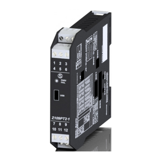
Manufacturer-unauthorised personnel on the module, or if the content of this user Manual is not followed. 2. DESCRIPTION AND CHARACTERISTICS 2.1 MODULE DESCRIPTION The Z109PT2-1 module acquires an thermoresistance input signal, converts it to an analog format and send it to an universal isolated output. 2.2 GENERAL CHARACTERISTICS AND FEATURES Thermoresistance input: NI100, PT100, PT500 and PT1000. -
Page 3: Input
INSULATIONS 1500V STANDARDS The module complies with the following standards: EN61000-6-4 (electromagnetic emission, in industrial environment) EN61000-6-2 (electromagnetic immunity, THERMO- ANALOG RESISTANCE in industrial environment) INPUT EN61010-1 (safety) Notes: POWERSUPPLY - Use with copper conductor. - Use in Pollution Degree 2 Environment 1500 V... -
Page 4: Preliminary Instructions For Use 4
Avoid placing signal cables near power cables and power appliances (inverters, motors, induction ovens etc...). 5.2 USB INTERFACE The module has a microUSB connector, you can configure it through APP and/or software. For more information please see www.seneca.it/products/z109pt2-1 Z109PT2 CU-A-MICROB CU-A-MICROB CU-A-MICRO-OTG 5.3 CONNECTIONS Please provide the module with supply voltage < 40 V... -
Page 5: Power Supply
THERMORESISTANCE INPUT RTD 2 wires RTD 3 wires RTD 4 wires 5.6 ANALOG OUTPUT RE-TRANSMITTED OUTPUT Voltage Generated External power current Supply current V output mA output mA output (4) Powered active output to be connected to passive inputs. (5) Unpowered passive output to be connected to active inputs. In order to select this feature please see: SETTINGS THROUGH INTERNAL JUMPERS. -
Page 6: Configuration 6
6. CONFIGURATION INPUT SELECTION / MEASURING SCALE You can select the type of input by setting SW1 DIP switches placed on the side of the module. Every type of input is matched to a certain number of beginning and end scale values which can be selected through SW2 DIP switches. -
Page 7: Start And End Setting At Will
START AND END SETTING AT WILL The START and END push-buttons under the SW2 DIP-switch group allow to set the beginning and end scale at will, within the scale pre-set through the dip-switches. To obtain this facility it is necessary to use a suitable signal generator, able to furnish the desidered values of beginning and end scale. -
Page 8: Jumpers Position
17.5 mm 100 mm 1112 PWR/ FAIL Z109PT2-1 Z109PT2-1 9. DECOMMISSIONING AND DISPOSAL Disposal of Electrical & Electronic Equipment (Applicable throughout the European Union and other European countries with separate collections programs). This symbol, found on your product or on its packaging, indicates that this product should not be treated as household waste when you wish to dispose of it.


Need help?
Do you have a question about the Z109PT2-1 and is the answer not in the manual?
Questions and answers