Table of Contents
Advertisement
Quick Links
INSTALLATION MANUAL
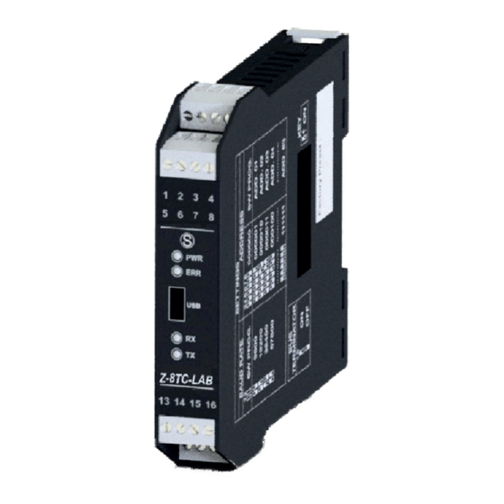
Z-8TC-LAB
Modbus RTU Module
with 8 ThermoCouple Inputs
EN
EN
SENECA s.r.l.
Via Austria, 26 – 35127 – PADOVA – ITALY
Tel. +39.049.8705355 - 8705359 - Fax +39.049.8706287
This document is property of SENECA rl. Duplication and reproduction are forbidden, if not authorized.
S
Contents of the present documentation refers to products and technologies described in it.
This informations may be modified or integrated for technical and / or commercial requirements.
MI005171-E
THE ORIGINAL VERSION IS IN ITALIAN LANGUAGE
ENGLISH
- 1/
8
Advertisement
Table of Contents

Related Manuals for Seneca Z-8TC-LAB


Summary of Contents for Seneca Z-8TC-LAB
- Page 1 Via Austria, 26 – 35127 – PADOVA – ITALY Tel. +39.049.8705355 - 8705359 - Fax +39.049.8706287 This document is property of SENECA rl. Duplication and reproduction are forbidden, if not authorized. Contents of the present documentation refers to products and technologies described in it.
-
Page 2: Module Description
Protection against electrostatic discharge (ESD) up to 4 kV. Programmable value in case of fault or freezing of last measurement. Easy power supply and serial bus wiring by means of the Seneca Z-BUS housed in the DIN rail. Removable screw terminals for section Max. 1.5 mm cable. -
Page 3: Technical Specifications
LED SIGNALLING ON FRONT PANEL State LEDs Meaning Power supply presence (Green) The device is powered off FAIL Fault or Failure: power supply lack, failed channel, failed (Yellow) hermocouple , internal communication error. RX (Red) Data reception from 485 communication port. TX (Red) Data transmission to 485 communication port. -
Page 4: Preliminary Warnings
The module may only be used by qualified and skilled technicians in the field of electric installation. Specific documentation is available for download at website: www.seneca.it/products/z-8tc-lab. Only the Manufacturer is authorized to repair the module or to replace damaged parts. -
Page 5: Installation Rules
PRELIMINARY WARNINGS Disposal of electrical & electronic equipment (applicable throughout the EU and other countries with separate collection programs). The symbol found on this product or on its packaging indicates that this product it must be handed over to an authorised collection point for the recycling of electrical and electronic equipments. -
Page 6: Electrical Connections
MODBUS CONNECTION STANDARDS 2 MODBUS Module 3 Module 4 Bus length Derivation Length Baudrate 1200 m 115kbps Module 1 Module 2 Module 5 In order to obtain maximum performances it’s Bus Length recommended to use a specific shielded cable, as DL: Derivation Length an example BELDEN 9841. -
Page 7: Modbus Registers
ELECTRICAL CONNECTIONS Connection for RS485 communication with the Modbus master system through Z-PC-DINAL2-17.5 accessory. RS485 Note: the indication of the RS485 connection polarity is not standardised IDC10 and in some masters may be inverted 2 8 TC INPUTS The module input accepts thermocouples type: J, K, E, N, S, R, B, T. -
Page 8: Dip-Switches Configuration
The USB communication port has priority over the port RS485 and is closed after 3 s of inactivity. The parameters (not configurable) for USB port are: 2400, 8,N,1 Addr. 1. The protocol is MODBUS RTU. CONTACTS Technical support support@seneca.it Product Informations sales@seneca.it ENGLISH - 8/8...
Need help?
Do you have a question about the Z-8TC-LAB and is the answer not in the manual?
Questions and answers