
Related Manuals for GEA DURIETTA 0


Summary of Contents for GEA DURIETTA 0
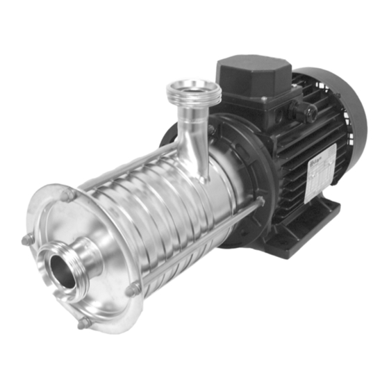
- Page 1 GEA Hilge DURIETTA 0 Installation and operating instructions English Translation of the original operating manual BA.012.KYY.001.03.17.GB engineering for a better world GEA Hilge...
- Page 2 Annex VII, Part B and we obligate to provide these upon reasoned request from the individual national authorities by data transfer. HILGE GmbH & Co.KG Authorized person for compiling and handing over Hilgestraße 37-47 technical documentation: 55294 Bodenheim, Germany Bodenheim, 2016-03-29 Franz Bürmann Managing Director GEA Hilge...
-
Page 3: Table Of Contents
1. Introduction _________________________________________________ 5 1.1 Target group_________________________________________________________________5 1.2 Symbols and formatting ________________________________________________________5 1.3 References to the document ____________________________________________________5 2. Safety ______________________________________________________ 6 2.1 Instructions for the operator _____________________________________________________6 2.1.1 General information_______________________________________________________6 2.2 Safety instructions in the operating manual _________________________________________6 2.3 Identification of instructions in the operating manual __________________________________7 2.3.1 Structure of safety instructions ______________________________________________7 2.4 Qualifications and training of personnel ___________________________________________8 2.5 Hazards caused by failure to follow the safety instructions _____________________________8... - Page 4 5. Start-up / shut-down__________________________________________ 26 5.1 Start-up ___________________________________________________________________ 26 5.1.1 Check application conditions ______________________________________________ 26 5.1.2 Starting up the pump ____________________________________________________ 26 5.1.3 Functional check of the mechanical seal _____________________________________ 26 5.2 Shut-down _________________________________________________________________ 27 5.2.1 Shutting down the pump __________________________________________________ 27 5.2.2 Cleaning the pump after shut-down _________________________________________ 27 6.
-
Page 5: Introduction
Introduction 1. Introduction Overview This section describes the requirements that are important for reading and understanding this manual. You will learn the symbols and formats that make the reading easier. 1.1 Target group This operating manual is intended for: • the operators of the pump •... -
Page 6: Safety
Safety 2. Safety Overview This section describes what you have to consider for your own safety. You will learn the structure and identifica- tion of safety instructions. Read this important section attentively! 2.1 Instructions for the operator All our pumps are professionally packed before they leave our 2.1.1 General information warehouse to avoid damage during transport. -
Page 7: Identification Of Instructions In The Operating Manual
Safety 2.3 Identification of instructions in the operating manual The safety instructions presented in this operating manual are Symbol identified as shown below. ATTENTION K.0319V1 | K.0320V1 Fig. 1 Symbol for safety intructions A: FailureL to follow these safety instructions can endanger personnel. B: Safety instructions which involve warnings against electrical voltage. -
Page 8: Qualifications And Training Of Personnel
Safety 2.4 Qualifications and training of The employees operating, maintaining, inspecting, and in- stalling the pump must have the appropriate qualifications for personnel this work. The operator must define in detail the tasks for which the employees are responsible, the tasks of which they are in charge, and the manner in which they are supervised. -
Page 9: Safety Instructions For The Operator / User
Safety 2.7 Safety instructions for the operator / user WARNING Hot or cold mechanical components! Serious bodily injury. Take structural measures to prevent contact with them! WARNING Trapping hazard! Death, serious bodily injury, damage to property. Do not remove protection against contact with moving parts (e.g. -
Page 10: Transport
Safety 2.10 Transport WARN ING Falling loads! Death, serious bodily injury, damage to property. Transport work must only be performed by persons quali- fied to do so, and all safety instructions must be observed. Use suitable load carrying equipment with sufficient ca- pacity to transport the pump. -
Page 11: Repair Contract
Safety 2.12 Repair contract The duty to follow the legal regulations on work safety and the regulations on environmental protection means that all com- mercial enterprises must protect their employees, the public at large, and the environment from the harmful effects of haz- ardous materials. -
Page 12: Product Description
Product description 3. Product description Overview This section describes the pump as well as it’s design and application. Section „Technical Data“ describes limits for application. You must know and keep these limits. 3.1 Pump overview 0107 0162 0680 0156 0107 0112 0801 0905... -
Page 13: Proper Usage
Product description 3.3 Proper usage WARNING Improper usage! Death, serious bodily injury, damage to property. Pump only media that are specified in the order. The pump has been specially designed for that purpose. Operate the pump only in the electrical network specified in the order. -
Page 14: Pump Denomination
Product description The HILGE pump denomination is structured as shown be- 3.4.1 Pump denomination low: 32/25 0.55 durietta pump type size design nominal diameter DN / DN power [kW] number of poles Tab. 1 HILGE pump denomination (example) The pump can be identified by the pump serial number. When 3.4.2 Pump serial number ordering spare parts, always state the pump serial number. -
Page 15: Weights
Product description Design features of the described standard pumps: 3.4.5 Weights Caution: The weights can - depending on design and accessories - dif- fer from those presented. The manufacturer gives you when given the pump / order number precise information. •... -
Page 16: Noise Emissions
Product description Measured values according to DIN EN ISO 3746 for pump 3.4.6 Noise emissions units; uncertainty of measurement 3dB (A). Motor power [dB (A) 1. Stage 2. Stage 3. Stage 4. Stage 5. Stage 6. Stage 0,55 0,75 Tab. 3 Noise emissions - 2 poles Motor power [dB (A) -
Page 17: Maximum Operating Pressure
Product description 3.4.8 Maximum operating pressure WARNING Pressure overload! Death, serious bodily injury, damage to property. The pump must be operated according to the order pdata. Never exceed the specified maximum operating pres- sures. The maximum permissible operating pressure depends on Pump operating pressure various factors: •... -
Page 18: Mounting, Installation And Connection
Mounting, installation and connection 4. Mounting, installation and connection Overview This section is intended for maintenance and repair personnel. This section describes how to mount, adjust and install the pump. You get to know what to consider when you connect the pump to the electric mains supply and how to improve the flow in order to avoid dry running of the shaft seals. -
Page 19: Installation In The Pipeline
Mounting, installation and connection Align the pump in this way: 1. Use an engineer’s spirit level laid across the machined surface of the discharge branch connection to align the assembly. 2. After aligning the assembly, tighten the mounting bolts uniformly in a crosswise manner. 4.3 Installation in the pipeline WARNING Mechanical overload! - Page 20 Mounting, installation and connection What is dry running? Details about dry running To seal the pump shaft against the pump casing the mechan- ical seal needs lubrication between its rotating faces. This lubrication is provided by the pumped liquid. If the pump is fitted with a quench, the lubrication for the quench must be provided from an external source.
-
Page 21: Space Requirements
Mounting, installation and connection K.0076V2 Fig. 5 Installation in the pipeline above: gravity feed mode below: suction mode P - pump M - motor 4.3.1 Space requirements WARNING Overheating! Damage to property. Ensure sufficient ventilation. Make sure not to reabsorb warm cooling air. Consider oth- er heat sources in the area. -
Page 22: Reduction Of Noise And Vibration
Mounting, installation and connection Noise and vibration are generated by the pulsating flow of the 4.3.2 Reduction of noise and vibration rotors and by the flow in pipes and fittings. The effect on the environment is subjective and depends on correct installation and the state of the remaining system. -
Page 23: Connections For Flushing System
Mounting, installation and connection 4.4 Connections for flushing system HILGE pumps with double mechanical seal are equipped with 4.4.1 Double mechanical seal a seal cartridge. The flushing fluid flows inside this seal cartridge. The connection must be carried out as shown in fig. 8. So you can ensure that the fluid can flush the mechanical seal effec- tively. -
Page 24: Electrical Connections
Mounting, installation and connection Ensure the functioning in this way: 1. Open feed line for flushing liquid 2. Bleed seal cartridge 3. Ensure unpressurised circulation. A pure liquid, compatible with the pumped liquid, serves as a flushing liquid. In case of abrasive media, provide a „lost“ flushing, i.e. where the flushing liquid is discharged directly. -
Page 25: Checking The Direction Of Rotation After Connection
Mounting, installation and connection 4.5.3 Checking the direction of rotation after connection ATTENTION Danger of dry running! Damage to property. Before checking the direction of rotation, fill and vent the pump. Connect the motor and briefly (for about 2 seconds) check the direction of rotation. -
Page 26: Start-Up / Shut-Down
Start-up / shut-down 5. Start-up / shut-down Overview This section describes how to start up and shut down the pump. You get to know which inspections contribute to failure-free operation and increased life of the pump. 5.1 Start-up 5.1.1 Check application conditions Check the application conditions of the pump in this way: 1. -
Page 27: Shut-Down
Start-up / shut-down 5.2 Shut-down 5.2.1 Shutting down the pump CA UTION Pressure surge! Death, serious bodily injury, damage to property. Always close shut-off devices slowly! A pressure surge is an abrupt pressure increase in the sys- tem. This pressure increase can - for example - be caused by a quick blocking of the flow in the discharge pipe. -
Page 28: Maintenance / Servicing
Maintenance / servicing 6. Maintenance / servicing Overview This section is intended for maintenance and repair personnel. This section gives important information about maintenance and servicing of the pump. Read this section before you carry out maintenance work or troubleshooting measures! 6.1 Safety instructions for maintenance, inspection and installation work... -
Page 29: Maintenance Of The Pump
Maintenance / servicing WARNING Missing protection and safety equipment! Death, bodily injury, damage to property. Immediately after completing the work, install the protec- tion and safety equipment and make sure it functions. CA UTION Improper tools! Damage to property. In accordance with the design standard (3A0.01 to 3A3.37), all tools, possible support surfaces, and other auxiliary materials must ensure that all parts of the pump can be assembled without damage (e.g. -
Page 30: Disassembly / Assembly
Maintenance / servicing 6.4 Disassembly / Assembly 6.4.1 Parts overview 0490.00 0513.00 0433.01 0107.00 0513.01 0433.00 0230.01 0112.02 0504.02 0230.02 0513.02 0922.00 0412.02 0162.00 0932.08 0934.03 0412.11 0927.00 0412.22 0412.12 0412.04 0680.00 0905.01 0970.01 0801.00 0920.70 0507.00 0340.00 0504.23 0920.00 0890.00 0211.00 0554.00... -
Page 31: Instructions For Disassembly
Maintenance / servicing 6.4.2 Instructions for disassembly Disregarding important instructions! Death, serious bodily injury, damage to property. Before you disassemble the pump note section 6.1, page Important aspects! Damage to property. Use tools from HILGE assembly tool kit in order to dis- assemble the pump without damage and scratches. -
Page 32: Disassembly Of The Pump
Maintenance / servicing Disassemble the pump in this way: 6.4.4 Disassembly of the pump 1. Unscrew and remove domed nuts 0927.00. 2. Remove suction cover 0162.00. MF-197 MF-198 Fig. 12 Suction cover fixing Fig. 13 Suction cover 3. Unscrew and remove impeller nut 0922.00 4. - Page 33 Maintenance / servicing 9. Remove spacer ring 0504.02 together with O- 10. Remove O-ring 0412.22. ring 0412.22. MF-168 Fig. 21 O-ring spacer ring. MF-167 Fig. 20 Spacer ring Depending on number of stages: repeat steps Remove rotary ring of mechanical seal 0433.00. 5.
- Page 34 Maintenance / servicing 18. Unscrew and remove tie bolts 0905.01. 19. Strike pin 0560.15 out of the shaft 0211.00. MF-105 MF-093 Fig. 29 Tie bolts Fig. 30 Grooved pin 20. Remove shaft 0211.00. 21. Remove O-ring 0412.64. BA.012.KYY.001.02.10.GB...
-
Page 35: Assembly Of The Pump
Maintenance / servicing Assemble the pump in this way: 6.4.5 Assembly of the pump 1. Slide the pump shaft 0211.00 onto the motor 2. Insert the pins 0560.15/0560.16 into the pump shaft. shaft 0211.00. MF-098 MF-100 Fig. 31 Pump shaft Fig. - Page 36 Maintenance / servicing 9. Insert the discharge casing 0107.00. 10. Adjust the discharge casing 0107.00 via dis- charge branch by using a spirit level. MF-090 Fig. 39 Discharge casing MF-112 Fig. 40 Discharge branch 11. Spray pump shaft 0211.00 with clean water. 13.
- Page 37 Maintenance / servicing 19. Fit booth O-rings 0412.22 into the spacer ring 20. Slide the spacer ring 0504.02 onto the pump 0504.02. shaft 0211.00. MF-127 MF-128 Fig. 47 O-ring Fig. 48 Spacer ring 21. Assemble the diffusor casing 0112.02. 22. Repeat steps 16 - 21 depending on numbers of pump stages.
- Page 38 Maintenance / servicing 29. Insert the insert ring 0513.02 and O-ring 30. Grease the threads of the tie bolts 0905.01. 0412.12. Use Klüberpaste UH1 84-201 from Hilge assem- Assemble the suction cover 0162.00. bly tool kit (pos. 6, fig. 59). 31.
-
Page 39: Troubleshooting
Maintenance / servicing 6.5 Troubleshooting Problem Cause Remedy 1. Incorrect electrical hook-up (two phases). 1. Check the electrical connections and cor- Pump does not 2. Wrong direction of rotation. rect them if necessary. deliver or deliv- 2. Reverse the phases of the power supply ers at a reduced 3. -
Page 40: Disposal
This product or parts of it must be disposed of in an environ- mentally sound way: 1. Use the public or private waste collection service. 2. If this is not possible, contact the nearest GEA Hilge company or service workshop. BA.012.KYY.001.02.10.GB... -
Page 41: Hilge Assembly Tool Kit
Maintenance / servicing 6.7 HILGE assembly tool kit Remove and install the mechanical seals safely and reliably by using tools of the HILGE assembly tool kit. K.0266V1 Fig. 59 HILGE assembly tool kit 6.7.1 Content and use Description Description assembly sleeve Ø 19 plastic socket spanner insert SW 10 spray bottle 12d mechanical seal installation sleeve Ø... -
Page 42: Certificate Of Non-Objection
Certificate of non-objection 7. Certificate of non-objection Overview This section contains a certificate of non-objection. In case of inspection or repair send the pump including this certificate to HILGE. 7.1 Certificate of non-objection The following pump and its accessories, together with this certificate of non-objection, are herewith contracted out by the undersigned for inspection/repair: •... - Page 44 Responsibility GEA-versity GEA Group is a global engineering company with multi-billion euro sales and operations in more than 50 countries. Founded in 1881, the company is one of the largest providers of innovative equipment and process technology. GEA Group is listed in the STOXX Europe 600 Index.
Need help?
Do you have a question about the DURIETTA 0 and is the answer not in the manual?
Questions and answers