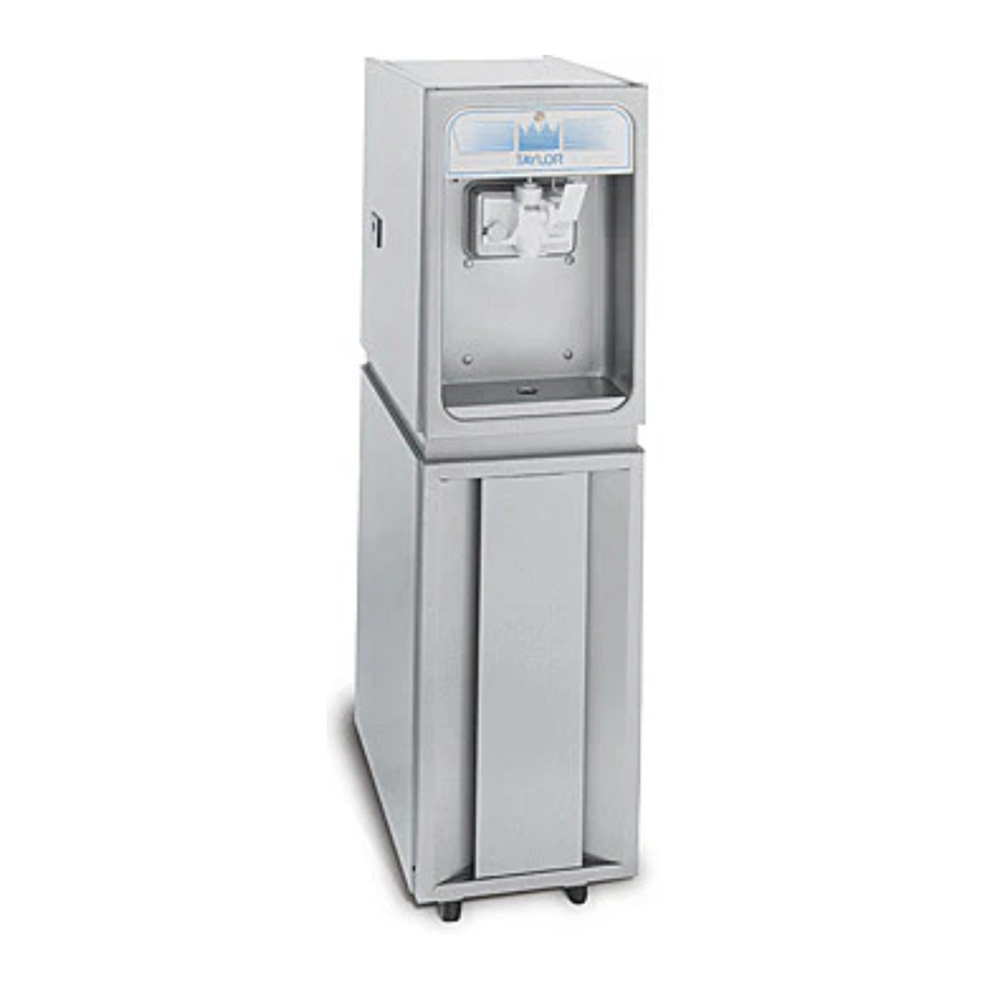
Taylor 150, 152, 162, 168 Manual
- Operator's manual (47 pages) ,
- Service manual (77 pages) ,
- Operator's manual (48 pages)
Advertisement
- 1 To the Installer
- 2 To the Operator
- 3 Operator Parts Identification
- 4 User Interface
- 5 Operating Procedures
- 6 Operator's Checklist
-
7
Troubleshooting Guide
- 7.1 No product being dispensed
- 7.2 The machine will not operate in the Auto mode
- 7.3 The product is too stiff
- 7.4 The product is too soft
- 7.5 The freezing cylinder walls are scored
- 7.6 Excessive leakage in rear drip pan
- 7.7 The draw valve is leaking
- 7.8 Product is not feeding into the freezing cylinder
- 7.9 The machine goes out on overload excessively
- 8 Parts Replacement Schedule
- 9 Safety
- 10 Documents / Resources
To the Installer
The following information has been included in the manual as safety and regulatory guidelines. For complete installation instructions, please see the Installation Checklist.
Installer Safety

In all areas of the world, machines should be installed in accordance with existing local codes. Please contact your local authorities if you have any questions.
Care should be taken to ensure that all basic safety practices are followed during the installation and servicing activities related to the installation and service of Taylor® machines.
- Only Taylor service personnel should perform installation, maintenance, and repairs on Taylor machines.
- Authorized service personnel should consult OSHA Standard 29CFRI910.147 or the applicable code of the local area for industry standards on lockout/tagout procedures before beginning any installation or repairs.
- Authorized service personnel must ensure that the proper personal protective equipment (PPE) is available and worn when required during installation and service.
- Authorized service personnel must remove all metal jewelry, rings, and watches before working on electrical equipment.

The main power supply(s) to the machine must be disconnected prior to performing any installation, maintenance, or repairs. Failure to follow this instruction may result in personal injury or death from electrical shock or hazardous moving parts, as well as poor performance or damage to the machine.
Note:
All repairs must be performed by a Taylor service technician.


This machine has many sharp edges that can cause severe injuries.
Site Preparation
Inspect the area where the machine is to be installed before uncrating the machine, making sure that all possible hazards the user or equipment may encounter have been addressed.
For Indoor Use Only: This machine is designed to operate indoors under normal ambient temperatures of 70°F to 75°F (21°C to 24°C). The machine has successfully performed in high ambient temperatures of 104°F (40°C) at reduced capacities.
Only install this machine in a location where its use and maintenance is restricted to trained personnel. Failure to comply may result in personal injury.

This machine must NOT be installed in an area where a water jet or hose can be used. NEVER use a water jet or hose to rinse or clean the machine. Failure to follow this instruction may result in electrocution.


This machine must be installed on a level surface to avoid the hazard of tipping. Extreme care should be taken in moving this machine for any reason. Two or more persons are required to safely move this machine. Failure to comply may result in personal injury or damage to the machine.
The authorized installer should inspect the machine and promptly report any damage to the local authorized Taylor distributor.
This machine is made using USA sizes of hardware. All metric conversions are approximate and vary in size.
Air-Cooled Machines
Models 150 and 152 require a minimum of 6 in. (152 mm) of clearance around both sides. Install the skirt provided on the right side of the machine and place the back of the machine against a wall to prevent recirculation of warm air. Model 162 requires 6 in. (152 mm) on all sides and the skirt installed on the rear of the machine. Model 168 requires 3 in. (76 mm) on all sides and the skirt installed on the rear of the machine. Minimum air clearances must be met to ensure adequate air flow for optimum performance. These machines are designed for indoor use only.


This machine must NOT be installed in an area where a water jet or hose can be used. NEVER use a water jet or hose to rinse or clean the machine. Failure to follow this instruction may result in electrocution.
Water Connections
(Water-Cooled Machines Only)
An adequate cold water supply must be provided with a hand shutoff valve. The water inlet and drain connections are located on the right side or the underside of the base. These connections are either 3/8 or 1/2 FTP, depending on the model of the machine. (Refer to the Model Specifications section for your unit.) Permanently connect the machine using 1/2 in. (12.7 mm) inside diameter water lines. Flexible lines are recommended if local codes permit their use. In Europe, hose sets for connection of appliances to the water mains must comply to the international IEC 61770 standard.
The water expansion valve setting should be set at 255 PSIG (1758 kPa).
Depending on local water conditions, it may be advisable to install a water strainer to prevent foreign substances from clogging the automatic water valve. There will be only one water-in and one water-out connection.
Do not install a hand shutoff valve on the water-out line!
Water should always flow in this order: first, through the automatic water valve; second, through the condenser; and third, through the outlet fitting to an open trap drain.
A backflow prevention device is required on the incoming water connection side. Please see the applicable national, state, and local codes for determining the proper configuration. Water pressure to the unit must not exceed 150 psi (1034 kPa).
Electrical Hookup Installation
For 60-Cycle, 1-Phase, Supplied with Cord and Plug
This equipment is supplied with a 3-wire cord and grounding type of plug for connection to a single-phase, 60-cycle, branch circuit supply. This machine must be plugged into a properly grounded receptacle. The cord and plug provided for 115/60/1 is 20 A; therefore, the wall outlet must also be 20 A. Check the data label, located on the side panel, for electrical specifications.
Permanent wiring may be employed if required by local codes. Instructions for conversion to permanent wiring are as follows:
- Make sure the freezer is electrically disconnected.
- Remove the appropriate panel and locate the small electrical box at the base of the freezer.
- Remove the factory-installed cord and strain relief bushing.
- Route incoming permanent wiring through 7/8 in. (22 mm) hole in base pan.
- Connect two power supply leads. Attach ground (earth) wire to the grounding lug inside the electrical box.
- Make sure the machine is properly grounded before applying power.
 FOLLOW YOUR LOCAL ELECTRICAL CODES.
Electrical Connections
For Models without Cord and Plug Supplied
Each freezer requires one power supply for each data label. Check the data label(s) on the freezer for branch circuit overcurrent protection or fuse, circuit ampacity, and electrical specifications. Refer to the wiring diagram provided inside the control box for proper power connections.
In the United States, this equipment is intended to be installed in accordance with the National Electrical Code (NEC) ANSI/NFPA 70-1987. The purpose of the NEC code is the practical safeguarding of persons and property from hazards arising from the use of electricity. This code contains provisions considered necessary for safety. Compliance therewith and proper maintenance will result in an installation essentially free from hazard! In all other areas of the world, equipment should be installed in accordance with the existing local codes.
Please contact your local authorities.

This machine must be properly grounded. Failure to do so can result in severe personal injury from electrical shock.
![]()
An equipotential grounding lug is provided with this machine. Some countries require the grounding lug to be properly attached to the rear of the frame by the authorized installer. The installation location is marked by the equipotential bonding symbol (5021 of IEC 60417-1) on both the removable panel and the machine's frame.
Avoid injury.
- DO NOT operate the machine unless it is properly grounded.
- DO NOT operate the machine with fuses larger than specified on the machine's data label.
- All repairs should be performed by an authorized Taylor service technician.
- The main power supplies to the machine must be disconnected prior to performing installation, repairs, or maintenance.
- For Cord-Connected Machines: Only Taylor service technicians or licensed electricians may install a plug or replacement cord on the machine.
- Machines that are permanently connected to fixed wiring and for which leakage currents may exceed 10 mA, particularly when disconnected or not used for long periods, or during initial installation, shall have protective devices to protect against the leakage of current, such as a GFI, installed by the authorized personnel to local codes.
- Stationary machines that are not equipped with a power cord and a plug or another device to disconnect the appliance from the power source must have an all-pole disconnecting device with a contact gap of at least 0.125 in. (3 mm) in the external installation.
- Supply cords used with this machine shall be oil-resistant, sheathed flexible cable not lighter than ordinary polychloroprene or other equivalent synthetic elastomer-sheathed cord (code designation 60245 IEC 57) installed with the proper cord anchorage to relieve conductors from strain, including twisting, at the terminals and protect the insulation of the conductors from abrasion.
- If the supply cord is damaged, it must be replaced by the manufacturer, service agent, or a similarly qualified person to avoid a hazard.
- Secure supply cord ground lead to machine in a location where if the cord is pulled the main power leads become taut before the ground lead can break loose.
Failure to follow these instructions may result in electrocution. Contact your local authorized Taylor distributor for service.
Beater Rotation
NOTICE!

Beater rotation must be clockwise as viewed looking into the freezing cylinder.
Note: The following procedures should be performed by a Taylor service technician.
To correct rotation on a three-phase machine, interchange any two incoming power supply lines at the freezer main terminal block only. To correct rotation on a single-phase machine, change the leads inside the beater motor. (Follow the diagram printed on the motor.)
Electrical connections are made directly to the terminal block provided in the splice box, mounted on the base pan on each side of Model 168 and located in the splice boxes mounted mid-level on the frame channel on the sides of Model 162.
Refrigerant

This machine contains fluorinated greenhouse gases (F-Gas) to provide refrigeration using a hermetically sealed circuit or within foam insulation. This machine's type of gas, quantity, Global Warming Potential (GWP), and CO2 tonnes equivalent information is recorded on the machine's data label. The refrigerant used is generally considered nontoxic and nonflammable. However any gas under pressure is potentially hazardous and must be handled with caution.
NEVER fill any refrigerant cylinder completely with liquid. Filling the cylinder approximately 80% will allow for normal expansion.
Use only approved refrigerant listed on the machine's data label or authorized through a manufacturer's technical bulletin. The use of any other refrigerant may expose users and operators to unexpected safety hazards.

Refrigerant liquid sprayed onto the skin may cause serious damage to tissue. Keep eyes and skin protected. If refrigerant burns should occur, flush the area immediately with cold water. If burns are severe, apply ice packs and contact a physician immediately.
NOTICE!

Taylor reminds technicians to be aware of and in compliance with local government laws regarding refrigerant recovery, recycling, and reclaiming systems. For information regarding applicable local laws, please contact your local authorized Taylor distributor.
Refrigerants and their associated lubricants may be extremely moisture absorbent. When opening a refrigeration system, the maximum time the system is open must not exceed 15 minutes. Cap all open tubing to prevent humid air or water from being absorbed by the oil.
To the Operator
The freezer you have purchased has been carefully engineered and manufactured to give you dependable operation. The Taylor Company models covered in this manual consist of the following: 150, 152, 162, and 168.
These units, when properly operated and cared for, will produce a consistent quality product. Like all mechanical products, they will require cleaning and maintenance. A minimum amount of care and attention is necessary if the operating procedures outlined in this manual are followed closely.
This manual should be read before operating or performing any maintenance on the machine.
Your Taylor machine will NOT compensate for and/or correct any errors made during setup or filling operations. Thus, the initial assembly, setup, and priming procedures are of extreme importance. It is strongly recommended that all personnel responsible for the machine's operation, including assembly and disassembly, go through these procedures together to be properly trained and to make sure that all personnel understand their role in using and maintaining the machine.
If you require technical assistance, please contact your local authorized Taylor distributor.
Note: Your Taylor warranty is valid only if the parts are authorized Taylor parts purchased from the local authorized Taylor distributor and if all required service work is provided by a Taylor service technician. Taylor reserves the right to deny warranty claims on units or parts if unapproved parts or incorrect refrigerant were installed in the unit, system modifications were performed beyond factory recommendations, or it is determined that the failure was caused by abuse, misuse, neglect, or failure to follow all operating instructions. For full details of your Taylor warranty, please see "Limited Warranty on Equipment" and "Limited Warranty on Parts".
Note: Constant research results in steady improvements. Therefore, information in this manual is subject to change without notice.
Operator Parts Identification
Model 150

| Item | Description | Part No. |
| 1 | Cover A.-Hopper | X48690 |
| 2 | Tube-Feed-.166 Hole-SS | 035819 |
| 3 | Float A.-Mix Level | X39690 |
| 4 | Panel-Back Top | 050429 |
| 5 | Panel-Upper Side Left | 030783-SS |
| 6 | Pan-Drip 11-5/8 Long | 027503 |
| 7 | Panel-Back Bottom | 050430 |
| 8 | Panel-Lower Side | 030792-SS |
| 9 | Panel-Insert | 025533-SS |
| 10 | Panel A.-Lower Front | X25518 |
| 11 | Tray-Drip | 025062 |
| 12 | Shield-Splash | 025063 |
| 13 | Decal-Dec | 047667 |
| 14 | Panel-Upper Side RT | 030784-SS |
| 15 | Light-Ambr-Rnd-12V-Mix Low | 039707 |
| 16 | Caster-3" Swv 4 Hole/Brk | 058500 |
| 17 | Panel A.-Front | X25036 |
| 18 | Trim-Top Back Panel | 025536 |
| 19 | Trim-Middle Back Panel | 025537 |
| 20 | Trim-Side and Front | 025528 |
| 21 | Plate-Dec | 041034-SS |
| 22 | Holder-Drip Tray | 035866 |
| 23 | Caster-3" Rgd-4 Hole Plate | 058501 |
Model 152

| Item | Description | Part No. | Item | Description | Part No. |
| 1 | Cover A.-Hopper | X48690 | 13 | Decal-Dec | 047667 |
| 2 | Tube-Feed-.166 Hole-SS | 035819 | 14 | Panel-Upper Side RT | 030784-SS |
| 3 | Float A.-Mix Level | X39690 | 15 | Light-Ambr-Rnd-12V-Mix Low | 039707 |
| 4 | Panel-Back Top | 050429 | 16 | Caster-3" Swv 4 Hole/Brk | 058500 |
| 5 | Panel-Upper Side Left | 030783-SS | 17 | Panel A.-Front | X25036 |
| 6 | Pan-Drip 11-5/8 Long | 027503 | 18 | Trim-Top Back Panel | 025536 |
| 7 | Panel-Back Bottom | 050430 | 19 | Trim-Middle Back Panel | 025537 |
| 8 | Panel-Lower Side | 030792-SS | 20 | Trim-Side and Front | 025528 |
| 9 | Panel-Insert | 025533-SS | 21 | Plate-Dec | 041034-SS |
| 10 | Panel A.-Lower Front | X25518 | 22 | Holder-Drip Tray | 035866 |
| 11 | Tray-Drip | 025062 | 23 | Caster-3" Rgd-4 Hole Plate | 058501 |
| 12 | Shield-Splash | 025063 |
Model 162

| Item | Description | Part No. | Item | Description | Part No. |
| 1 | Cover A.-Hopper | X37963-SER | 11 | Tray-Drip-16-7/8 x 4-3/8 | 030565 |
| 2 | Tube-Feed-.166 Hole | 030797 | 12 | Panel-Front Right | 035933-SS |
| 3 | Float A.-Mix Level | X39690 | 13 | Trim-Front | 050212-SS |
| 4 | Panel-Rear | 047276-SS | 14 | Panel-Front Left | 035932-SS |
| 5 | Panel-Side-Left | 050213-SS | 15 | Leg-4.250 (With O-ring) | 013458 |
| 6 | Pan-Drip 19-1/2 Long | 035034 | 16 | Panel-Side Right | 050214-SS |
| 7 | Panel A.-Front | X30711 | 17 | Trim-Panel-Rear | 035923 |
| 8 | Light-Amber-Round Mix Low | 039707 | 18 | Plate-Decorative | 039723-SS |
| 9 | Decal-Decorative-Taylor | 047666 | 19 | Holder-Drip Tray | 035866 |
| 10 | Shield-Splash | 030789 |
Model 168

| Item | Description | Part No. | Item | Description | Part No. |
| 1 | Cover A.-Hopper | X37963-SER | 12 | Panel-Upper Side Right | 030784-SS |
| 2 | Tube-Feed-.166 Hole SS | 030797 | 13 | Insert-Front Panel | 030773-SS |
| 3 | Float A.-Mix Level | X39690 | 14 | Panel A.-Lower Front | X30747 |
| 4 | Panel-Top Back | 030790-SS | 15 | Panel-Bottom Back | 055833 |
| 5 | Panel-Upper Side Left | 030783-SS | 16 | Caster-3 Rigid (Rear) | 012226 |
| 6 | Pan-Drip 17-1/4 Long | 027504 | 17 | Caster-3 Swivel (Front) | 012227 |
| 7 | Panel A.-Front | X30711 | 18 | Panel-Lower Side-Right/Left | 030792-SS |
| 8 | Light-Amber-Round Mix Low | 039707 | 19 | Trim-Top Back Panel | 030775 |
| 9 | Decal-Decorative-Taylor | 047666 | 20 | Trim-Middle Back Panel | 030795 |
| 10 | Shield-Splash 17-5/8 Long | 030789 | 21 | Plate-Decorative | 039723-SS |
| 11 | Tray-Drip 16-7/8 Long | 030565 | 22 | Holder-Drip Tray | 035866 |
Models 150 and 152 Door Assembly

Figure 4-5
| Item | Description | Part No. | Item | Description | Part No. |
| 1 | Valve-Draw | 024763 | 8 | Door A.-1 Spout | X38959-SER |
| 2 | O-ring-7/8 OD x.103 W | 014402 | 9 | Bearing-Guide | 014496 |
| 3 | O-ring-3/4 OD x.103 W | 015835 | 10 | O-ring-2-3/4 OD x.139 W | 019998 |
| 4 | Handle-Draw | 024762 | 11 | Bearing-Front | 023262 |
| 5 | Arm-Valve Lifter | 024761 | 12 | Beater A. | X24689 |
| 6 | Nut-Stud | 034829 | 13 | Seal-U-Cup | 080534 |
| 7 | Cap-Design 1.010 ID - 6 Point | 014218 |
Models 162 and 168 Door Assembly

| Item | Description | Part No. | Item | Description | Part No. |
| 1 | Valve-Draw | 024763 | 8 | Cap-Design 1.010 ID - 6 Point | 014218 |
| 2 | O-ring-7/8 OD x.103 W | 014402 | 9 | Pin A.-Pivot Long | X38538 |
| 3 | Seal-Draw Valve (H-ring) | 030930 | 10 | Valve-Draw-Center | 031164 |
| 4 | Kit A.-Door 3 Spt 1.5 Qt. Valox | X56906-SER | 11 | Bearing-Guide | 014496 |
| 4a | Nut-Stud | 056802 | 12 | O-ring-2-3/4 OD x.139 W | 019998 |
| 5 | Pin A.-Pivot Short | X38539 | 13 | Bearing-Front | 023262 |
| 6 | O-ring-5/16 OD x.070 W | 016272 | 14 | Beater A. | X24689 |
| 7 | Handle-Draw Valve | 030564 | 15 | Seal-U-Cup | 080534 |
Models 150 and 152 Accessories

| Item | Description | Part No. | Item | Description | Part No. |
| 1 | Kit A.-Tune Up | X25802 | 5 | Brush-Mix Pump Body-3 x 7 White | 023316 |
| 2 | Brush-Rear Bearing 1 x 2 | 013071 | 6 | Pail-6 Qt. | 023348 |
| 3 | Brush-Double-Ended | 013072 | *7 | Sanitizer-Stera-Sheen® | See Note |
| 4 | Brush-Draw Valve 1 OD x 2 x 17 | 013073 | 8 | Lubricant-Taylor 4 oz. | 047518 |
*Note: A sample container of sanitizer is sent with the unit. For reorders, order Stera-Sheen® part no. 055492 (100 2 oz. packs) or Kay-5® part no. 041082 (200 packs).
Models 162 and 168 Accessories

| Item | Description | Part No. | Item | Description | Part No. |
| 1 | Kit A.-Tune Up | X31167 | 5 | Brush-Mix Pump Body-3 x 7 | 023316 |
| 2 | Brush-Rear Bearing 1 x 2 | 013071 | 6 | Pail-6 Qt. | 023348 |
| 3 | Brush-Double Ended | 013072 | *7 | Sanitizer | See Note |
| 4 | Brush-Draw Valve 1 x 2 x 17 | 013073 | 8 | Lubricant-Taylor 4 oz. | 047518 |
*Note: A sample container of sanitizer is sent with the unit. For reorders, order Stera-Sheen part no. 055492 (100 2 oz. packs) or Kay-5 part no. 041082 (200 packs).
User Interface

| Item | Description | Item | Description |
| 1 | Reset Button | 4 | Mix Refrigeration Switch |
| 2 | Power Switch | 5 | Indicator Lights - MIX LOW |
| 3 | Temperature Control |
Symbol Definitions
To better communicate in the international arena, the words on many of our operator switches and buttons have symbols to indicate their functions. Your Taylor machine is designed with these international symbols.
The following chart identifies the symbol definitions used on the operator switches.
 | ON/AUTO |  | WASH |
 | ON |  | STANDBY |
 | OFF |
Reset Button
If an overload condition occurs, the freezer will automatically stop operating. To properly reset the freezer:
- Place the toggle switch in the OFF position.
- Wait two or three minutes, then press the reset button.
- Place the power switch in the WASH position and observe the freezer's performance.
- Place the power switch in the AUTO position.
Note: If the freezer is unplugged from the wall receptacle, it will be necessary to press the reset button for the freezer to operate once power is re-established.
Power Switch
The center position is OFF. The left position is WASH, which activates only the beater motor. The right position is AUTO, which activates the beater motor and the refrigeration system.
Feed Tube
Models 150, 152, 162, and 168 are called upon to handle a large variety of products (i.e., soft serve, yogurts, Italian ices, sherbets, etc.). Thus, the consistency of the mix you use will vary. The feed tube meters a combination of mix and air into the freezing cylinder. If not enough mix enters the freezing cylinder, a freeze-up may occur, which will cause eventual damage to the beater. Depending upon the product you are running, you may wish to contact your local Taylor-authorized distributor to make a slight adjustment to the feed tube.

Figure 5-2
Note: During Auto operation, the orifice end of the tube should be inserted in the hole in the hopper.
Taylor Quality Control
These machines use a solid state control called the TQC. The purpose of this solid state control is to sense the viscosity (thickness) of the product in the freezing cylinder. With the power switch in the AUTO position, the TQC will automatically keep the mix in the freezing cylinder at the proper viscosity and ready for serving.
Indicator Light—MIX LOW
A mix level indicating light is located at the front of the machine. When the light is on, it indicates that the mix hopper has a low supply of mix and should be refilled as soon as possible. Always maintain at least 2 in. (5.1 cm) of mix in the hopper. If you neglect to add mix, a freeze-up may occur. This will cause eventual damage to the beater assembly and to the freezer door.
Mix Refrigeration Switch
The Mix Refrigeration switch is under the control channel and is used for several purposes:
- For the machine to operate in the Auto mode, the mix refrigeration switch must be ON.
- For the separate hopper refrigeration system to operate, the mix refrigeration switch must be in the ON or STANDBY positions.
- For the cylinder temperature retention system to operate, the power switch must be in the AUTO position, and the Mix Refrigeration switch must be in the STANDBY position.
Separate Hopper Refrigeration (SHR)
This feature incorporates the use of a separate, small refrigeration system to chill (on a limited basis) the mix in the hopper and to maintain the mix's temperature below 40°F (4.4°C). It also ensures bacterial control. To activate this system, place the power switch in the AUTO position and the mix refrigeration switch in the ON position. To operate this system in the Standby mode, place the power switch in the AUTO position and the mix refrigeration switch in the STANDBY position.
Cylinder Temperature Retention (CTR)
To maintain a good quality product during long no sale periods, it will be necessary to warm the product in the freezing cylinder to approximately 35°F to 40°F (1.7°C to 4.4°C). This will prevent overbeating and product breakdown. The CTR is used in conjunction with the SHR to ensure that the mix in the freezing cylinder is refrigerated during the Standby mode of operation.
To operate the Standby mode of operation:
Place the power switch in the AUTO position and the mix refrigeration switch in the STANDBY position. With sanitized hands, remove the feed tube. Turn it over and place the end without the hole into the mix inlet hole.
To resume normal operation:
Leave the power switch in the AUTO position and place the Mix Refrigeration switch in the AUTO position. When the machine cycles off, the product in the freezing cylinder will be the correct viscosity. With sanitized hands, remove the feed tube. Turn it over and place the end with the hole into the mix inlet hole.
Operating Procedures
Model 150 has been selected to illustrate the pictured step-by-step operating procedures. All models in this manual are similar. They each have a 1.5 qt. (1.4 L) capacity freezing cylinder. The mix flows by gravity from the hopper to the freezing cylinder through a feed tube.
Note:
- Model 150 is a console model with a single-spout door.
- Model 152 is a counter model with a single-spout door.
- Model 162 is a counter model, and Model 168 is a console model. Both have three-spout doors. Two individual flavors are available from the end spouts, and an equal combination of both is dispensed through the center spout to create a twist effect.
We begin our instructions at the point when we enter the store in the morning and find the parts disassembled and laid out to air-dry from the previous night's cleaning. These opening procedures will show how to assemble these parts to the freezer, sanitize them, and prime the freezer with fresh mix in preparation to serve the first portion.
Note: For Models 162 and 168, duplicate the procedures where they apply for the second freezing cylinder.


If you are disassembling the machine for the first time or need information to get to the starting point in our instructions, turn to "Disassembly", and start there.
Assembly

Make sure the power switch is in the OFF position. Failure to follow this instruction may result in severe personal injury from hazardous moving parts.
Note:
When lubricating parts, use an approved food-grade lubricant (example: Taylor Lube).
- Lubricate the groove on the beater driveshaft. With the opening of the cup seal facing away from the hex end, slide the seal into the groove. Apply an even coat of lubricant to the seal and the shaft.Do not lubricate the hex end of the beater driveshaft.

Figure 6-5 - Insert the beater assembly through the rear shell bearing at the back of the freezing cylinder and engage the hex end firmly into the female socket. When properly seated, the beater will not protrude beyond the front of the freezing cylinder.

Figure 6-6
Note: Repeat this step for the second freezing cylinder on Models 162 and 168. - Place the large O-ring(s) into the groove(s) on the back of the freezer door and lubricate with Taylor Lube.

Figure 6-7 - Slide the front bearing(s) over the baffle rod(s) so that the flanged edge is against the door. Place the white plastic guide bearing(s) on the end of the baffle rod(s).
Do not lubricate the front bearing(s) or the guide bearing(s).

Figure 6-8 - Slide the slotted portion of the handscrews into the slots in the freezer door.
- With both hands, hold the sides of the freezer door and insert the baffle rod(s) into the center of the beater assembly(ies). The white guide bearing(s) must fit securely in the hole(s) of the driveshaft(s).
- Finger-tighten the handscrews, making sure they are tightened equally and that the door is secure.Do not overtighten the handscrews.
![]()
Handscrew and door damage can result if the handscrews are overtightened or if one handscrew is tightened more than the other. - Slide the two O-rings into the grooves on the draw valve(s) and lubricate with Taylor Lube.

Figure 6-9
Note: For Models 162 and 168, install the valve seal in the grooves on the center draw valve and lubricate with Taylor Lube. This special seal will prevent mix from one freezing cylinder from traveling into the second cylinder.

Figure 6-10 - Lubricate the inside of the freezer door spout(s) from the bottom. Insert the draw valve(s) into the freezer door from the bottom.

Figure 6-11
Note: The draw valve is installed correctly when the slotted opening in the draw valve is visible through the window of the freezer door.

Figure 6-12 - Slide the O-ring into the groove on the draw valve handle and lubricate.

Figure 6-13 - Insert the valve lifter arm through the slotted opening in the draw valve and align the other end with the cross holes of the freezer door.
- Insert the draw valve handle through the opposite cross hole and into the opening of the valve lifter arm.
Note: The draw valve handle can be assembled at varied vertical positions. Choose an angle which is comfortable for you. The draw valve must be raised completely when the draw valve handle is down.

Figure 6-14
Note: For Models 162 and 168, slide the O-ring onto each pivot pin and lubricate.

Figure 6-15
Note: Models 162 and 168 have three draw handles. Slide the tip of the draw handle into the slot of the draw valve, starting from the right. Slide the short pivot pin through the far right draw handle. Slide the long pivot pin through the far left and middle draw handles.

Figure 6-16 - Snap the design cap(s) over the bottom of the freezer door spout(s).

Figure 6-17 - Install the front drip tray and splash shield under the freezer door.

Figure 6-18 - Lay the feed tube(s) in the bottom of the mix hopper(s).


Sanitizing
- Prepare an approved 100 ppm sanitizing solution (examples: Kay-5® or Stera-Sheen®). Use warm water and follow the manufacturer's specifications.
- Pour 1 gal. (3.8 L) of the sanitizing solution into the hopper and allow it to flow into the freezing cylinder.
- While the solution is flowing into the freezing cylinder, brush-clean the mix hopper, mix level float stem, mix inlet hole, and feed tube.


- Press the reset button.

Figure 6-22 - Place the power switch in the WASH position. This will cause the sanitizing solution in the freezing cylinder to be agitated. Allow it to agitate for 5 minutes.

Figure 6-23 - Place an empty pail beneath the door spout and raise the draw valve. Draw off all of the sanitizing solution. When the sanitizer stops flowing from the door spout, lower the draw valve and place the power switch in the OFF position.

Figure 6-24
Note: On Models 162 and 168, momentarily pull down the center draw handle to sanitize the center door spout. - With sanitized hands, stand the feed tube in the corner of the mix hopper. Place the mix level float on the mix level float stem.

Figure 6-25 - Repeat step 1 through step 7 for the second freezing cylinder on Models 162 and 168.


Priming
Prime the machine as close as possible to the time of first product draw.
- With a pail beneath the door spout, raise the draw valve. Fill the mix hopper with fresh mix. (The maximum hopper capacity is 8 qt. [7.6 L].) Allow the mix to flow into the freezing cylinder. This will force out any remaining sanitizing solution. When full-strength mix is flowing from the door spout, lower the draw valve.
Note: Use only fresh mix when priming the freezer.

Figure 6-26 - When the mix has stopped bubbling down into the freezing cylinder, with sanitized hands install the feed tube withn the mix inlet hole. Make sure the small hole in the feed tube is down.

Figure 6-27 - Place the mix hopper cover in position.
- Place the mix refrigeration switch in the ON position.

Figure 6-28 - Place the power switch in the AUTO position.

Figure 6-29 - Momentarily raise the draw switch paddle to activate the refrigeration cycle. When the machine cycles off, the product will be ready to serve.
- Repeat the applicable steps for the second freezing cylinder on Models 162 and 168.
- Slide the rear drip pan into the hole in the side panel.


Closing Procedure
To disassemble Models 150, 152, 162, or 168, the following items will be needed:
- Two cleaning pails
- Sanitized stainless steel rerun can with lid
- Cleaning brushes (provided with freezer)
- Cleaners
- Single-service towels
Draining Product from the Freezing Cylinder
- Place the mix refrigeration switch and the power switch in the OFF positions as far ahead of cleaning time as possible. This will allow frozen product to soften for easier cleaning.
- If local health codes permit the use of rerun, place a sanitized, NSF-approved, stainless-steel rerun container beneath the door spout. Place the power switch in the WASH position and raise the draw valve. When all the product stops flowing from the door spout, lower the draw valve and place the power switch in the OFF position. Place a sanitized lid on the rerun container and place it in the walk-in cooler.
Note: For additional information regarding the proper use of rerun, see "Troubleshooting Bacterial Count".
If local health codes do not permit the use of rerun, the product must be discarded. Follow the instructions in the previous step, except drain the product into a pail and properly discard the mix.
![warning]() ALWAYS FOLLOW LOCAL HEALTH CODES.
ALWAYS FOLLOW LOCAL HEALTH CODES. - Lift the hopper cover. Remove the feed tube and mix level float. Take them to the sink for cleaning.
- Repeat step 1 through step 3 for the second freezing cylinder on Models 162 and 168.
Rinsing
- Pour 1 gal. (3.8 L) of cool, clean water into the mix hopper. With the brushes provided, scrub the mix hopper, the mix level float stem, and the mix inlet hole.
- With a pail beneath the door spout, place the power switch in the WASH position and raise the draw valve. Drain all the rinse water from the freezing cylinder. When the rinse water stops flowing from the door spout, lower the draw valve and place the power switch in the OFF position.
Repeat this procedure until the rinse water being drawn from the freezing cylinder is clear. - Repeat step 1 and step 2 for the second freezing cylinder on Models 162 and 168.
Cleaning
- Prepare an approved cleaning solution (examples: Kay-5® or Stera-Sheen®). Use warm water and follow the manufacturer's specifications.
- Pour 1 gal. (3.8 L) of the cleaning solution into the mix hopper and allow it to flow into the freezing cylinder.
- While the solution is flowing into the freezing cylinder, brush-clean the mix hopper, mix level float stem, and mix inlet hole.
- Place the power switch in the WASH position. This will cause the cleaning solution in the freezing cylinder to agitate.
- Place an empty pail beneath the door spout and raise the draw valve. Draw off all the cleaning solution. When the solution stops flowing from the door spout, lower the draw valve and place the power switch in the OFF position.
- Repeat step 1 through step 5 for the other side of the freezer on Models 162 and 168.
Disassembly

Make sure the power switch is in the OFF position. Failure to follow this instruction may result in severe personal injury from hazardous moving parts.
- Remove the handscrews and the freezer door. Remove the beater assembly(ies) from the freezing cylinder(s).
- Remove the front drip tray and the splash shield.
- Remove the rear drip pan from the side panel.
Note: If the drip pan is filled with an excessive amount of mix, this is an indication that the drive shaft cup seal of the beater assembly should be replaced or properly lubricated. - Take these parts to the sink for cleaning.
Brush-Cleaning
- Prepare a sink with an approved cleaning solution (examples: Kay-5® or Stera-Sheen®). Use warm water and follow the manufacturer's specifications.
![]()
Follow label directions, since too strong of a solution can cause parts damage, while too mild of a solution will not provide adequate cleaning. Make sure all brushes provided with the freezer are available for brush-cleaning. - Remove the cup seal(s) from the driveshaft(s) of any beater assemblies.
- From the freezer door, remove the design cap, draw valve handle, valve lifter arm, and draw valve.
Remove all O-rings.
Models 162 and 168: From the freezer door, remove design caps, pivot pins, draw handles, draw valves, and the center draw valve. Remove all O-rings.
Note: To remove the O-rings, use a single-service towel to grasp the O-ring. Apply pressure upward until the O-ring pops out of its groove. With the other hand, push the top of the O-ring forward. It will roll out of the groove and can be easily removed. If more than one O-ring needs to be removed, always remove the rear O-ring first to allow the O-ring to slide over the forward rings without falling into the open grooves. - Remove the front bearing(s), and remove the guide bearing(s) from the back of the freezer door.
- Thoroughly brush-clean all disassembled parts in the cleaning solution. Make sure all lubricant and mix film is removed. Take particular care to brush-clean the draw valve core(s) in the freezer door. Place all the cleaned parts on a clean, dry surface to air-dry overnight.
- Return to the freezer with a small amount of cleaning solution. With the black bristle brush, brush-clean the rear shell bearing(s) at the back of the freezing cylinder(s).

Figure 6-31 - Wipe clean all exterior surfaces of the freezer.

Operator's Checklist
During Cleaning and Sanitizing
 ALWAYS FOLLOW LOCAL HEALTH CODES.
Cleaning and sanitizing schedules are governed by federal, state, or local regulatory agencies, and must be followed accordingly. If the machine has a Standby mode, it must not be used instead of proper cleaning and sanitizing procedures and frequencies set forth by the ruling health authority. The following checkpoints should be stressed during the cleaning and sanitizing operations.
Cleaning and sanitizing must be performed daily.
Troubleshooting Bacterial Count
- Thoroughly clean and sanitize the machine regularly, including complete disassembly and brush-cleaning.
- Use all brushes supplied for thorough cleaning. The brushes are specially designed to reach all mix passageways.
- Use the smaller, white bristle brush to clean the mix inlet hole that extends from the mix hopper down to the rear of the freezing cylinder.
- Use the black bristle brush to thoroughly clean the rear shell bearing located at the rear of the freezing cylinder. Make sure to use a generous amount of cleaning solution on the brush.
- If local health codes permit the use of rerun, make sure the mix rerun is stored in a sanitized, covered stainless-steel container and is used the following day. Do not prime the machine with rerun. When using rerun, skim the foam and discard. Mix the rerun with fresh mix in a ratio of 50:50 during the day's operation.
- On a designated day of the week, run the mix as low as feasible and discard after closing. This will break the rerun cycle and reduce the possibility of high bacteria and coliform counts.
Operator's Checklist
- Properly prepare the cleaning and sanitizing solutions. Read and follow label directions carefully. Too strong of a solution may damage the parts, and too weak of a solution will not do an adequate job of cleaning or sanitizing.
- Make sure the temperature of the mix in the mix hopper and walk-in cooler is below 40°F (4.4°C).
Regular Maintenance Checks
- Check the rear shell bearing for signs of wear (excessive mix leakage in rear drip pan) and make sure it is properly cleaned.
- Using a screwdriver and cloth towel, clean the rear shell bearing and the female hex drive socket of lubricant and mix deposits.
- Dispose of O-rings or seals if they are worn, torn, or fit too loosely, and replace them with new ones.
- Follow all lubricating procedures as outlined in "Assembly".
- If your machine is air-cooled, check the condenser for dirt and lint. A dirty condenser will reduce the efficiency and capacity of the machine. Condensers should be cleaned monthly with a soft brush. Never use screwdrivers or other metal probes to clean between the fins. Failure to comply may result in electrocution.
Note: For machines equipped with an air filter, it will be necessary to vacuum-clean the filters on a monthly. - On the auxiliary refrigeration system, check the condenser for dirt and lint. A dirty condenser will reduce the refrigeration capacity of the mix hopper. Condensers must be cleaned monthly with a soft brush. Never use screwdrivers or other metal probes to clean between the fins. Failure to comply may result in electrocution.
Winter Storage
If the place of business is to be closed during the winter months, it is important to protect the freezer by following certain precautions, particularly if the building is subject to freezing conditions.
- Disconnect the freezer from the main power source to prevent possible electrical damage. Your local Taylor distributor can perform this service for you.
- Wrap detachable parts of the freezer, such as the beater assembly and freezer door, and place them in a protected, dry place. Rubber trim parts and gaskets can be protected by wrapping them with moisture-proof paper.
All parts should be thoroughly cleaned of dried mix or lubrication accumulations, which can attract mice and other vermin.
Troubleshooting Guide
Table 8-1
| Problem | Probable Cause | Remedy |
No product being dispensed |
|
|
The machine will not operate in the Auto mode |
|
|
The product is too stiff |
|
|
The product is too soft |
|
|
The freezing cylinder walls are scored |
|
|
Excessive leakage in rear drip pan |
|
|
The draw valve is leaking |
|
|
Product is not feeding into the freezing cylinder |
|
|
The machine goes out on overload excessively |
|
|
| Models 162 and 168: Mix from one freezing cylinder bleeds over to the second cylinder. |
|
|
Parts Replacement Schedule
Maintenance Intervals
Table 9-1
| Part Description | Every 3 Months | Every 6 Months | Annually | Qty. | |
| 150/152 | 162/168 | ||||
| Beater Driveshaft Cup Seal | X | 1 | 2 | ||
| Freezer Door O-ring | X | 1 | 2 | ||
| Freezer Door Front Bearing | X | 1 | 2 | ||
| Freezer Door Guide Bearing | X | 1 | 2 | ||
| Draw Valve O-ring | X | 2 | 4 | ||
| Draw Valve Handle O-ring | X | 1 | - | ||
| Center Draw Valve Seal | X | - | 1 | ||
| Pivot Pin O-ring | X | - | 2 | ||
| Black Bristle Brush, 1" x 2" | Inspect and replace if necessary. | Minimum | 1 | 1 | |
| Double Ended Brush | Inspect and replace if necessary. | Minimum | 1 | 1 | |
| White Bristle Brush, 1" x 2" | Inspect and replace if necessary. | Minimum | 1 | 1 | |
| White Bristle Brush, 3" x 7" | Inspect and replace if necessary. | Minimum | 1 | 1 | |
Safety
We at the Taylor Company are concerned about the safety of the operator when he or she comes into contact with the freezer and its parts. Taylor has gone to extreme efforts to design and manufacture built-in safety features to protect both you and the service technician. As an example, warning labels have been attached to the freezer to further point out safety precautions to the operator.

Failure to adhere to the following safety precautions may result in severe personal injury or death. Failure to comply with these warnings may also damage the machine and/or its components. Such damage may require component replacement and service repair expenses.
NOTICE!

DO NOT operate this machine without reading this entire manual first. Failure to follow all of these operating instructions may result in damage to the machine, poor performance, health hazards, or personal injury.
This machine is to be used only by trained personnel. It is not intended for use, cleaning, or maintenance by children or people with reduced physical, sensory, or mental capabilities or lack of experience and knowledge, unless given supervision or instruction concerning the use of the machine by a person responsible for their safety. Children should be supervised to ensure that they do not play with the machine.
![]()
An equipotential grounding lug is provided with this machine. Some countries require the grounding lug to be properly attached to the rear of the frame by the authorized installer. The installation location is marked by the equipotential bonding symbol (5021 of IEC 60417-1) on both the removable panel and the machine's frame.

This machine must NOT be installed in an area where a water jet or hose can be used. NEVER use a water jet or hose to rinse or clean the machine. Failure to follow this instruction may result in electrocution.
Avoid injury.
- DO NOT operate the machine unless it is properly grounded.
- DO NOT operate the machine with fuses larger than specified on the machine's data label.
- All repairs should be performed by an authorized Taylor service technician.
- The main power supplies to the machine must be disconnected prior to performing installation, repairs, or maintenance.
- For Cord-Connected Machines: Only Taylor service technicians or licensed electricians may install a plug or replacement cord on the machine.
- Machines that are permanently connected to fixed wiring and for which leakage currents may exceed 10 mA, particularly when disconnected or not used for long periods, or during initial installation, shall have protective devices to protect against the leakage of current, such as a GFI, installed by the authorized personnel to local codes.
- Stationary machines that are not equipped with a power cord and a plug or another device to disconnect the appliance from the power source must have an all-pole disconnecting device with a contact gap of at least 0.125 in. (3 mm) in the external installation.
- Supply cords used with this machine shall be oil-resistant, sheathed flexible cable not lighter than ordinary polychloroprene or other equivalent synthetic elastomer-sheathed cord (code designation 60245 IEC 57) installed with the proper cord anchorage to relieve conductors from strain, including twisting, at the terminals and protect the insulation of the conductors from abrasion.
- If the supply cord is damaged, it must be replaced by the manufacturer, service agent, or a similarly qualified person to avoid a hazard.
- Secure supply cord ground lead to machine in a location where if the cord is pulled the main power leads become taut before the ground lead can break loose.
Failure to follow these instructions may result in electrocution. Contact your local authorized Taylor distributor for service.

Avoid injury.
- DO NOT allow untrained personnel to operate this machine.
- DO NOT put objects or fingers in the door spout.
- DO NOT operate the machine unless all service panels and access doors are fastened with screws.
- DO NOT remove the machine door or beater assembly unless the control switches are in the OFF position.
Failure to follow these instructions may result in severe personal injury from hazardous moving parts.

This machine has many sharp edges that can cause severe injuries.
- DO NOT put objects or fingers near the shaver or the pitcher blades.
- USE EXTREME CAUTION when removing blades that are very sharp.
Failure to follow this instruction may result in contaminated product or personal injury from blade contact.

This machine must be placed on a level surface. Use caution when moving the machine.
Failure to comply may cause the machine to tip over and result in personal injury.
Only install this machine in a location where its use and maintenance is restricted to trained personnel. Failure to comply may result in personal injury.
NOTICE! Cleaning and sanitizing schedules are governed by your federal, state, or local regulatory agencies and must be followed accordingly. Please refer to the cleaning section of this manual for the proper procedure to clean this machine.
This machine is designed to maintain product temperature under 41°F (5 ºC). Any product being added to this machine must be below 41 ºF (5 ºC). Failure to follow this instruction may result in health hazards and poor machine performance.
Do not obstruct air intake and discharge openings:
- 150 and 152: Minimum of 6 in. (152 mm) of clearance around both sides. Install the skirt provided on the right side of the machine and place the back of the machine against a wall to prevent recirculation of warm air.
- 162: Minimum of 6 in. (152 mm) on all sides. Install the skirt provided on the rear of the machine.
- 168: Minimum of 3 in. (76 mm) on all sides. Install the skirt provided on the rear of the machine.
For Indoor Use Only: This machine is designed to operate indoors under normal ambient temperatures of 70°F to 75°F (21°C to 24°C). The machine has successfully performed in high ambient temperatures of 104°F (40°C) at reduced capacities.
Do not run the machine without product. Failure to follow this instruction can result in damage to the machine.
Noise Level: Airborne noise emission does not exceed 78 dB(A) when measured at a distance of 3.3 ft. (1.0 m) from the surface of the machine and at a height of 5.25 ft. (1.6 m) from the floor.
Documents / ResourcesDownload manual
Here you can download full pdf version of manual, it may contain additional safety instructions, warranty information, FCC rules, etc.
Advertisement


Need help?
Do you have a question about the 150 and is the answer not in the manual?
Questions and answers