
Related Manuals for Taylor 0736


Summary of Contents for Taylor 0736
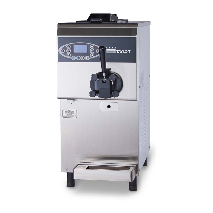
- Page 1 OPERATOR’S MANUAL Model 0736 Counter Top Heat Treatment Soft Serve Freezer Original Operating Instructions 02/08/2018 (Original Publication) 087827-M (Updated 5/22/2019)
- Page 2 Only instructions originating from the factory or its authorized translation representative(s) are considered to be the original set of instructions. © 2018 Taylor Company (Updated 5/22/2019) 087827-M Any unauthorized reproduction, disclosure, or distribution of copies by any person of any portion of this work may be a violation of Copyright Law of the United States of America and other countries, could result in the awarding of ...
-
Page 3: Table Of Contents
Table of Contents Section 1: To the Installer Installer Safety ....................1-1 Site Preparation ....................1-1 Air-Cooled Machines..................1-2 Water Connections..................... 1-2 Electrical Connections..................1-2 Electrical Hookup Installation ................1-3 Beater Rotation ....................1-3 Refrigerant ......................1-4 Indications for Decommissioning ............... 1-4 Section 2: To the Operator Operator Information .................. - Page 4 Section 5: User Interface Symbol Definitions....................5-2 LCD Display .......................5-2 Indicator Icons on the Display and Buttons ............5-2 Operating Screen Description ................5-3 Main Power Switch OFF..................5-3 Main Power Switch ON ..................5-3 Heat Cycle......................5-3 Freezer Locks.....................5-4 Manager's Menu....................5-5 Manager Menu Options..................5-5 Section 6: Operating Procedures Assembly......................6-1 Sanitizing......................6-7 Priming .......................6-8...
-
Page 5: Section 1: To The Installer
Failure to comply may result in personal damage to the machine. injury or machine damage. Note: All repairs must be performed by a Taylor service Uncrate the machine and inspect it for damage. Report technician. any damage to your Taylor distributor. -
Page 6: Air-Cooled Machines
The installation location is marked by the equipotential bonding symbol (5021 of IEC 60417-1) on the removable panel and the machine’s frame. To the Installer Model 0736... -
Page 7: Electrical Hookup Installation
The following procedures should be performed by a a similarly qualified person, in order to avoid a Taylor service technician. hazard. To correct rotation on a three-phase machine, interchange any two incoming power supply lines at freezer main terminal block only. -
Page 8: Refrigerant
If burns are severe, apply ice packs and contact a physician immediately. NOTICE! Taylor reminds technicians to be aware of government laws regarding refrigerant recovery, recycling, and reclaiming systems. If you have any questions regarding these laws, please contact the factory service department. -
Page 9: Section 2: To The Operator
Operator Information Note: Constant research results in steady improvements; therefore, information in this manual is The Model 0736 soft serve freezer has been carefully subject to change without notice engineered and manufactured to give you dependable operation. This machine is suitable for food mixtures heat treatment, storage and batch, according to use allowed by law. -
Page 10: Compressor Warranty Disclaimer
It should also be noted that Taylor does not warrant the refrigerant used in its products. For example, if the refrigerant is lost during the course of ordinary service to... -
Page 11: Section 3: Safety
We at the Taylor Company are concerned about the safety of the operator when he or she comes into contact with the freezer and its parts. Taylor has gone to extreme efforts to design and manufacture built-in safety features WARNING! This machine has many sharp to protect both you and the service technician. -
Page 12: Machine Warning Labels
• If the supply cord is damaged, it must be replaced by the manufacturer, service agent, or Only authorized Taylor service personnel should perform a similarly qualified person, in order to avoid a installation and repairs on this machine. hazard. - Page 13 Battery type CR2032 inside. For decommissioning, comply with the standards in force in the country where it is used. Water pressure limits (for water-cooled models only). Use only R404A refrigerant that conforms to the AHRI Standard 700 specification. Safety Model 0736...
- Page 14 Glycol with the described dilution. Equipotential Point Label Carry out an equipotential bonding, using the screw placed below the frame of the machine. Lifting Point Label Lift equipment hooking points. Position the lifting equipment only in the relevant points. Safety Model 0736...
-
Page 15: Section 4: Operator Parts Identification
Operator Parts Identification Section 4 Main View Figure 4-1 Operator Parts Identification Model 0736... - Page 16 087734 Stud-Nose Cone 087722 Agitator-Hopper 087735 Panel-Front-Upper 087723 Cap-Agitator 087875 Pan-Drip 087724 Tube-Feed 087737 Shelf-Tray-Drip 087725 Coupling-Feed Tube 087738 Tray-Drip 087726 O-ring-Feed Tube 087762 Shield-Splash 087727 Valve-Check- Duckbill-Pump 087742 O-ring - Baffle - Door 087745 Operator Parts Identification Model 0736...
-
Page 17: Front - Panel
Figure 4-2 Item Description Part No. Item Description Part No. Panel - Front - Lower 087719 Tray - Drip 087726 Guide - Drip - Pan 087713 Shelf - Tray - Drip 087725 Shield - Splash 087727 Operator Parts Identification Model 0736... -
Page 18: Single Spout Door Assembly
Item Description Part No. Item Description Part No Handle-Draw-Black 087740 Nut-Stud-Door 087748 Valve-Draw 087741 O-ring-Handle Pin 087749 O-ring-Draw Valve 087743 Screw-Adjustmt-Handle 087750 O-ring-Door-Large 087744 Spacer-Screw-Adjustmt 087751 Pin-Draw Handle-SS 087746 Handle-Body 087752 Door-Freezer 087747 O-ring-Handle-Body 087753 Operator Parts Identification Model 0736... -
Page 19: Beater Assembly
087732 O-ring - Baffle 087730 Beater - Auger 087728 Bearing - Door - Baffle 087731 Beater - 2 - Liter 87733 O-ring - Baffle - Door 087745 Seal - Beater - Drive - Shaft 087734 Operator Parts Identification Model 0736... -
Page 20: Control - Main
OPERATOR PARTS IDENTIFICATION Control - Main Figure 4-5 Item Description Part No Thermostat 087948 Control - Main 087948-58 Probe - Thermistor 087957 Operator Parts Identification Model 0736... -
Page 21: 3-Way-Valve
Hose - Rubber 5/16” ID x 9/16” OD 047340F60 Valve - 3 Way 087946 Adaptor - 1/4MP x 5/16 Barb-BR 047326F Elbow - 1/4 MP x 5/16 Barb -Brass 047327F Bracket - Valve 087947 Clamp - Hose 35/64 - Stepless EA 087730 Operator Parts Identification Model 0736... -
Page 22: Mix Pump Assembly
Figure 4-7 Item Description Part No. Item Description Part No. Cover-Pump 087754 Valve-Pump 087765 O-ring Pump Body 087755 Spring-Regulator 087761 Gears-Mix Pump Set 087756 O-ring-Feed Tube 087762 Body-Pump 087758 Tube-Regulator 087763 O-ring-Pump 087759 Nut-Stud-Pump 087764 Operator Parts Identification Model 0736... -
Page 23: Tune Up Kit
OPERATOR PARTS IDENTIFICATION Tune Up Kit Figure 4-8 Item Description Part No. Item Description Part No. Kit-Tune Up *0736* 087774 Bearing-Door-Baffle 087731 O-ring-DEL Tube/Regulator 087762 Cap-Agitator 087875 O-ring-Pump 087759 O-ring-Handle-Pin 087749 O-ring-Baffle 087730 O-ring-Handle-Body 087753 O-ring-Draw-Valve 087743 O-ring-Door-Small 087745 Valve-Check-Duckbill-Pump... -
Page 24: Brush Assembly
OPERATOR PARTS IDENTIFICATION Brush Assembly Figure 4-9 Item Description Part No Kit-Brush *0736* 087805 Brush-Hopper 087805-A Brush-Mix Inlet 087805-B Brush-Drive Hub 087805-C 4-10 Operator Parts Identification Model 0736... -
Page 25: Section 5: User Interface
ON, indicating that the product is ready to be delivered. The number indicates the consistency of the product and can be adjusted from 60 to 250. High numbers correspond to high consistencies, low numbers correspond to lower consistencies. Figure 5-1 User Interface Model 0736... -
Page 26: Symbol Definitions
Your Taylor machine is operator if a fault is detected. The display indicates also designed with these international symbols. -
Page 27: Operating Screen Description
When the machine is powered, the control system will in the process of a Heat cycle. initialize to perform a system check. The screen will display the Taylor logo for a few seconds. Standby Button The Standby feature maintains product temperatures in Main Power Switch OFF both the hopper and the barrel below 40°F (4.4°C). -
Page 28: Freezer Locks
Heat Treatment Cycle. The following screen will be displayed if a brush-clean Note: A record of Heat Cycle Data and Lockout History cycle time has occurred: can be found in the Manager's Menu (SEL button). Figure 5-5 User Interface Model 0736... -
Page 29: Manager's Menu
The partial counter will automatically reset to zero when the machine is cleaned; you can also reset this counter manually by selecting the OK button to confirm the operation. The total counter cannot be reset by the operator. Figure 5-7 Figure 5-6 User Interface Model 0736... - Page 30 Arrow buttons to increase or decrease the value. Press the OK button to confirm the value and to advance to the Figure 5-11 next entry. Enter the correct minutes and press the OK button to save and return to the main menu. User Interface Model 0736...
- Page 31 The fluid level is too low to operate; switch off the DEFECTIVE TRANSFORMER) Press the STOP button machine. Call your Taylor service technician. and switch off the machine. Call your Taylor service TEV INT.—(ALARM—PROBE TEV INTERRUPTED) The technician. hopper thermistor is open; switch off the machine. Call DEV.
- Page 32 150 °F (65.6°C). • OVER—Total time the hopper (H) and barrel (B) HP 15C—The mix temperature in the hopper exceeded temperature was above 150 °F (65.6°C). 59°F (15°C). BR 15C—The mix temperature in the barrel exceeded 59°F (15°C). User Interface Model 0736...
- Page 33 Heat cycle stored. System Information The SYSTEM INFORMATION screen displays the machine’s part number, the LCD version, and the main board’s software release date. Press the C button to return to the main menu. Figure 5-15 User Interface Model 0736...
- Page 34 USER INTERFACE Notes: 5-10 User Interface Model 0736...
-
Page 35: Section 6: Operating Procedures
When lubricating parts, use an approved food 3. Lightly lubricate both sides of the beater driveshaft grade lubricant (example: Taylor Lube). MAKE SURE seal. Slide this seal up to the stop. Do not lubricate THE MACHINE IS DISCONNECTED! Failure to follow the square end. - Page 36 OPERATING PROCEDURES 3. Lightly lubricate the inside of the top of the freezer door valve cavity. Figure 6-4 Freezer Door Assembly 1. Place the door O-ring into the groove on the back of the freezer door. Figure 6-7 Note: If the draw valve is inserted with the flat surface facing the user, this will prevent the machine from operating.
- Page 37 OPERATING PROCEDURES 5. Insert the counter-beater on the rear pin on the freezer door and rotate it until the pins align with the holes in the door. Place the counter-beater O-ring into the groove on rear pin of the freezer door. Figure 6-11 8.
- Page 38 OPERATING PROCEDURES 10. Position the draw handle with the adjustment screw Mix Pump Assembly facing down. Slide the ball of the draw handle into the 1. Inspect the rubber and plastic pump parts. The slot of the draw valve. Secure the draw handle to the O-rings must be in 100% good condition for the pump door using the pivot pin.
- Page 39 OPERATING PROCEDURES 4. Lubricate the interior surfaces of the pump body 7. Install the pump cover on the pump body studs. (the rear wall, pin, and bushing). Note: The pump cover holes have different diameters to prevent incorrect assembly. Install the handscrews and tighten them equally to make sure the pump is closed.
- Page 40 OPERATING PROCEDURES Feed Tube Assembly 1. Slide one feed tube O-ring into the groove on the bushing and lubricate. Figure 6-24 Figure 6-27 10. Insert the liquid regulator into the hole located on the Note: Make sure the valve is properly seated in the bottom of the pump cover, aligning the notch with the tube.
-
Page 41: Sanitizing
OPERATING PROCEDURES Sanitizing 3. Place the feed tube coupling onto the feed tube until it reaches the stop position. 1. Prepare an approved 100 PPM sanitizing solution ® or 2 gal. (example: 2-1/2 gal. [9.5 L] of Kay-5 ® [7.6 liters] of Stera-Sheen ). -
Page 42: Priming
OPERATING PROCEDURES 4. Install the assembled feed tube in the mix inlet in the bottom of the hopper. Connect the other end of the feed tube to the outlet of the pump. Secure the feed tube in place by rotating the feed tube coupling. Make sure that the regulator tube is set to the correct position for the desired overrun. -
Page 43: Daily Closing Procedures
OPERATING PROCEDURES 5. Press the Wash button. Open and close the draw Important! Make sure the agitator is installed and the valve six times to complete the priming procedure. switch is in the Auto or Standby/Storage mode or the machine will not have a successful Heat cycle. Note: Use extreme caution when opening the draw 7. -
Page 44: Daily Opening Procedures
OPERATING PROCEDURES Daily Opening Procedures Draining Product From the Barrel 1. With a pail beneath the door spout, open the draw Before performing the opening procedures, check the valve to release the barrel pressure. Press the Wash display panel for any error messages. If a fault has been button and wait for a few seconds. -
Page 45: Disassembly
OPERATING PROCEDURES Hopper Cleaning 2. Remove the scraper blades and the beater head from the beater. 1. Prepare an approved 100 PPM sanitizing solution ® 3. Remove the driveshaft seal from the beater. or 2 gal. (example: 2-1/2 gal. [9.5 L] of Kay-5 ®... -
Page 46: Adjustments
OPERATING PROCEDURES Adjustments Hopper Temperature Adjustment in Auto Mode 1. With a machine loaded with fresh mix, press the For best performance carefully read the following Auto button to start with the freezing cycle. instructions before proceeding. 2. Press the Auto and Option buttons simultaneously for Consistency Adjustment a few seconds until the adjustment menu appears on 1. - Page 47 OPERATING PROCEDURES Hopper Agitation Adjustment in Auto Mode Hopper Temperature Adjustment in Standby Mode 1. With the machine filled with fresh mix, press the Auto 1. With the machine filled with a fresh mix, press the button to start the freezing cycle. Standby button.
- Page 48 OPERATING PROCEDURES Hopper Agitation Adjustment in Standby Mode 4. Subsequent parameters allow the operator to change the operating times (MIXING ON) and pause 1. With the machine filled with fresh mix, press the (MIXING OFF) of the hopper agitator motor during Standby button.
-
Page 49: Section 7: Operator Checklist
Condensers should be cleaned monthly with a cylinder. Use a generous amount of cleaning soft brush. Never use screwdrivers or other metal solution on the brush. probes to clean between the fins. Operator Checklist Model 0736... -
Page 50: Winter Storage
Condensers must be cleaned severe and costly damage to the refrigeration system. monthly with a soft brush. Never use Your local Taylor distributor can perform this service for screwdrivers or other metal probes to clean you. between the fins. Failure to comply may result in •... -
Page 51: Section 8: Troubleshooting Guide
Select Auto and allow machine to cycle off before drawing product. c. Beater motor is off during over c. Press the STOP button and wait temperature. The message 5 minutes. Restart the machine in appears on the display. Auto mode. Troubleshooting Guide Model 0736... - Page 52 Beater shaft seal improperly - - - 13. Excessive mix leakage a. Lubricate or replace the seal. into the long drip pan. lubricated or worn. Troubleshooting Guide Model 0736...
- Page 53 (turn it to the left). c. Draw rate is set too fast. c. Adjust draw rate. - - - d. Barrel not primed correctly. d. Drain the barrel and prime the machine. Troubleshooting Guide Model 0736...
- Page 54 TROUBLESHOOTING GUIDE Notes: Troubleshooting Guide Model 0736...
-
Page 55: Section 9: Parts Replacement Schedule
Pump Gear Set *Mix Pump Actuator Belt *Glycol Fluid Inspect and Brush-Drive Hub replace if Minimum necessary. Inspect and Brush-Mix Inlet replace if Minimum necessary. Inspect and Brush-Hopper replace if Minimum necessary. *Call an authorized service techincian. Parts Replacement Schedule Model 0736... - Page 56 PARTS REPLACEMENT SCHEDULE Notes: Parts Replacement Schedule Model 0736...
-
Page 57: Section 10: Limited Warranty On Machines
Taylor, through a Taylor-authorized Taylor distributor or service agency, will provide a new or remanufactured part, at Taylor's option, to replace the failed defective part at no charge for the part. Except as otherwise stated herein, these are Taylor's exclusive obligations under this limited warranty for a Product failure. This limited warranty is subject to all provisions, conditions, limitations, and exclusions listed below and on the reverse (if any) of this document. - Page 58 7. Failure, damage, or repairs due to faulty installation, misapplication, abuse, no or improper servicing, unauthorized alteration, or improper operation or use as indicated in the Taylor Operator's Manual, including but not limited to the failure to use proper assembly and cleaning techniques, tools, or approved cleaning supplies.
- Page 59 LEGAL REMEDIES The owner must notify Taylor in writing by certified or registered letter to the following address of any defect or complaint with the Product, stating the defect or complaint and a specific request for repair, replacement, or other correction of the Product under warranty, mailed at least thirty (30) days before pursuing any legal rights or remedies.
- Page 60 LIMITED WARRANTY ON MACHINES Notes: 10-4 Limited Warranty on Machines Model 0736...
-
Page 61: Section 11: Limited Warranty On Parts
Taylor warrants the Parts against failure due to defect in materials or workmanship under normal use and service as follows. All warranty periods begin on the date of original installation of the Part in the Taylor product. If a Part fails due to defects during the applicable warranty period, Taylor, through an authorized Taylor distributor or service agency, will provide a new or remanufactured Part, at Taylor's option to replace the failed defective Part at no charge for the Part. - Page 62 Taylor. 5. Replacement of wear items designated as Class 000 Parts in the Taylor Operator's Manual, as well as any release sheets and clips for the Product's upper platen assembly.
- Page 63 LEGAL REMEDIES The owner must notify Taylor in writing by certified or registered letter to the following address of any defect or complaint with the Part, stating the defect or complaint and a specific request for repair, replacement, or other correction of the Part under warranty, mailed at least thirty (30) days before pursuing any legal rights or remedies.
- Page 64 LIMITED WARRANTY ON PARTS Notes: 11-4 Limited Warranty on Parts Model 0736...
Need help?
Do you have a question about the 0736 and is the answer not in the manual?
Questions and answers