
Related Manuals for Taylor 104


Summary of Contents for Taylor 104
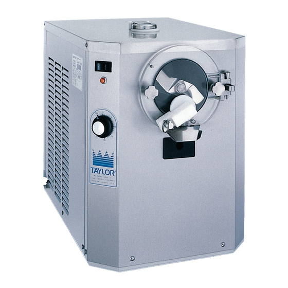
- Page 1 Models 104/220 Batch Freezers Service Manual 028763- -S 7/16/01 (Original Publication) (Updated 1/27/12)
-
Page 3: Table Of Contents
..........Model 104 Panels Exploded View . - Page 4 ........... . CAUTION: Information in this manual is intended to be used by Taylor Authorized Service Technicians only.
-
Page 5: Section 1: Introduction
Section 1: Introduction Safety Specifications Running Specifications General Installation Instructions Environmental Notices Models 104 & 220 Introduction... -
Page 6: Safety
The many built--in safety features that are including twisting, at the terminals and part of all Taylor equipment are aimed at protecting protect the insulation of the conductors from operators and trained service technicians alike. - Page 7 Operator Manual for the proper result in electrocution to the user or damage to the procedure to clean this unit. equipment. Models 104 & 220 Introduction...
-
Page 8: 104 Specifications
Crated:204 lbs. (92.5 kgs.) Maximum Minimum Fuse Size Circuit Ampacity 115/60/1 Air This unit is designed and constructed to meet stringent 208-230/60/1 Air safety and sanitation requirements for NSF and other 220-240/50/1 Air food service regulatory agencies. Introduction Models 104 & 220... -
Page 9: 220 Specifications
208--230/60/3 Air Crated:590 lbs. (267.6 kgs.) 208--230/60/3 Water 220--240/50/1 Air This unit is designed and constructed to meet stringent safety and sanitation requirements for NSF and other 220--240/380--415/ 50/3 Air food service regulatory agencies. 090811 Models 104 & 220 Introduction... -
Page 10: Running Specifications
(high suction pressure). The Model 104 will be approximately 28 PSI. The Model 220 will be Note: Make this adjustment with mix in the freezing approximately 22 PSI. -
Page 11: General Installation Instructions
Please contact your local authorities if you have any questions. The Model 104 requires a minimum of 6” (152 mm) and the Model 220 requires a minimum of 3” (76 mm) of air clearance around all sides of the freezer. - Page 12 Stationary appliances which are not equipped with a power cord and a plug or IMPORTANT: Do not install a shut- -off valve on the another device to disconnect the appliance drain line. 110908 Introduction Models 104 & 220...
- Page 13 (Follow the directions printed on the beater motor.) To correct rotation on a three--phase unit, interchange any two incoming power supply lines at freezer main terminal block only. (Follow the directions printed on the beater motor.) Models 104 & 220 Introduction...
- Page 14 Main Compressor: Model 104: Air Cooled Units - 26 oz. of R404a (HP62). Model 220: Air Cooled Units - 50 oz. of R404a (HP62). Model 220: Water Cooled Units -- 38 oz. of R404a (HP62).
-
Page 15: Environmental Notices
Environmental Notices _________________________________ The user is responsible for returning the product to the In consideration of our environment, Taylor proudly appropriate collection facility, as specified by your local uses only earth friendly HFC refrigerants. The HFC code. refrigerant used in this unit is R404A. This refrigerant... - Page 16 Notes: Introduction Models 104 & 220...
-
Page 17: Section 2: Controls
Section 2: Controls Models 104 & 220 Controls... -
Page 18: Controls
NOT operate if the door is open. Timer Control Control Switch The Model 104 uses a timer control to operate the compressor and determine the viscosity of the When the control switch is placed in the AUTO mode product. After the desired amount of product has been... - Page 19 Reset Condition and temperatures are dependent on specific mix formulations, pre-charge amounts and finished The Model 104 is equipped with an internal motor product preferences. overload protection. Should an overload occur, the Note: Because the freezing cylinder for the first batch reset mechanism will trip, cancelling freezer operation.
- Page 20 When the control switch is in the AUTO position, words on many of our operator switches and buttons this light will come on, indicating the refrigeration have symbols to indicate their functions. Your Taylor system is operating. equipment is designed with these International symbols.
-
Page 21: Section 3: Troubleshooting
Section 3: Troubleshooting General Troubleshooting Electrical Troubleshooting Models 104 & 220 Troubleshooting... -
Page 22: General Troubleshooting
Replace switch. 5. Poor ejection. a. Over refrigeration. a. Use less time to run the batch. b. Inadequate pre-charge b. Increase the pre-charge. c. The beater is rotating c. Correct the beater rotation to clockwise. counterclockwise. Troubleshooting Models 104 & 220... - Page 23 Replace the bearing. c. There is improper lubrication c. Lubricate properly. on the beater drive shaft. 8. The buzzer does not sound a. The buzzer is malfunctioning. a. Replace the buzzer. when the unit cycles off. Models 104 & 220 Troubleshooting...
- Page 24 Replace the drive shaft, drive socket, or both. Do not lubricate drive socket, or both. the hex end of the drive shaft. 8. Walls of freezer cylinder are a. Scraper blades were improperly a. Install them properly. scored. installed. Troubleshooting Models 104 & 220...
- Page 25 Improper priming procedures. c. Follow priming procedures. 12. Buzzer does not sound when a. Buzzer is malfunctioning. a. Replace the buzzer. the freezer cycles off. (Note: The buzzer is an optional feature.) Models 104 & 220 Troubleshooting...
-
Page 26: Model 104 Electrical Troubleshooting
Model 104 Electrical Troubleshooting Following are the paths of power necessary for Eject Mode of Operation component operation. L1 power must first pass through the HPCO switch to Auto Mode of Operation the control switch (terminals 5 and 6) and then to the coil of the beater relay. -
Page 27: Model 220 Electrical Troubleshooting
Then it goes to the temperature control. The temperature control must be set for L1 to pass through the control switch terminals 4 and 5 and reach the beater motor contactor. L1 going through the temperature control also reaches the compressor contactor. Models 104 & 220 Troubleshooting... - Page 28 Notes: Troubleshooting Models 104 & 220...
-
Page 29: Section 4: Parts
Section 4: Parts Parts Warranty Exploded Views Parts Lists Wiring Diagrams Models 104 & 220 Parts... -
Page 30: Warranty Explanation
Class 000 Parts: Wear Items - no warranty. CAUTION: Warranty is valid only if required service work is provided by an Authorized Taylor Service Technician. NOTE: Taylor reserves the right to deny warranty claims on equipment or parts if a non- -approved refrigerant was installed in the machine, system modifications were performed beyond factory recommendations, or it is determined that the failure was caused by neglect or abuse. - Page 31 Notes: Models 104 & 220 Parts...
-
Page 32: Model 104 Exploded View
Model 104 Exploded View Parts Models 104 & 220... - Page 33 Model 104 Parts Identification ITEM DESCRIPTION PART NO. ITEM DESCRIPTION PART NO. SHELL A.-INSULATED X33380 BRACKET-FAN 051036 BEARING-REAR SHELL 031324 BOX-SPLICE 051053 WASHER-BEARING LOCK 012864 COVER-SPLICE BOX 011858 NUT-BRASS BEARING 028991 SUPPORT-SHELL 051037 GUIDE-DRIP SEAL 028992 049009 FAN-5 BLADE 12” PUSH 22...
-
Page 34: Model 104 Panels Exploded View
Model 104 Panels Exploded View ITEM DESCRIPTION PART NO. ITEM DESCRIPTION PART NO. PANEL-SIDE *L 051039 HINGE·COVER·ASSY·ADAPTOR 037707 HOOD A. X51044 PANEL A.-FRONT X51043 PANEL-REAR 051040 PAN-DRIP 13-1/4 LONG 039027 PANEL-SIDE *R 051038 DECAL-DEC 051046-60 SCREW-10-32X3/8·TRUSS·HD 024298 STUD-FREEZER DOOR 023057 Parts Models 104 &... -
Page 35: Model 104 Beater Door Assembly
Model 104 Beater Door Assembly ITEM DESCRIPTION PART NO. ITEM DESCRIPTION PART NO. SEAL--DRIVE SHAFT 032560 SPOUT A.--DRIP X33422 SHAFT--BEATER 033498 NUT--STUD 008614 BEATER ASSEMBLY X33417 O--RING 2--1/4 OD X .139 W 030890 BLADE--SCRAPER 7--1/4” L 033277 PLATE--DRAW 027811 O--RING 5--7/16 OD X 5--1/4 ID... -
Page 36: Model 220 Exploded View
Model 220 Exploded View Parts Models 104 & 220... - Page 37 033027 BUSHING-MOUNTING 012258 RUBBER LIGHT-ORANGE-ROUND 017450 HINGE A.-MOTOR X25703 SCREW-6-32X5/8 RHM-STNLS 019309 SCREW-5/16-18 X 2-3/4 HEX 004191 BRACKET-ROCKER SWITCH 020820 CAP-RUBBER MOUNT 011844 SWITCH-ROCKER-DPDT 014237 ON-OFF-ON SPRING-COMP.970X.115X2.00 025707 CARD-SW-EJECT/OFF/AUTO 027910 GROMMET-7/16 X 5/16 SHOCK 016212 Models 104 & 220 Parts...
-
Page 38: Model 220 Panels Exploded View
Model 220 Panels Exploded View 100330 Parts Models 104 & 220... - Page 39 X68090 BUSHING-PANEL 013289 DECAL-DEC 021872 PANEL-UPPER SIDE R. 033125 PLATE-DEC 033027 PAN-DRIP 11-5/8 LONG 027503 PANEL-UPPER SIDE L. 033124 TRIM-REAR CORNER L. 031894 HINGE-CROSSBAR 007296 TRIM-REAR CORNER R. 031895 SCREW-HINGE 007245 SCREW-1/4-20X3/8 RHM-SLS 011694 100330 Models 104 & 220 Parts...
-
Page 40: Model 220 Beater Door Assembly
O-RING-2-1/8 OD X .139W-#225 020051 BEATER A. X32269 PISTON-VALVE 030083 BLADE-SCRAPER 052586 PIN-HINGE X04329 SHAFT-BEATER 032276 PIN A.-PIVOT X34737 SEAL-DRIVE SHAFT 031316 DOOR A.-PARTIAL SPOUT X32938 SCREW A.-CROSS BAR X07233 CAP A.-COVER X29667 BAR-CROSS 011740 Parts Models 104 & 220... -
Page 41: Cap & Relay Box X53471--27 (Model 220)
CONNECTOR-BX 3/8 STR 001791 CAPACITOR-START- 033044-1 CONNECTOR-BX 3/8 90D 001793 189-227UF/33 BUSHING-ANTI-SHORT 3/8 019117 BOX-CAPACITOR RELAY 030183 GREENFIELD-3/8 020495-27 COVER-CAP.RELAY BOX 030315 CONNECTOR-BX 3/8 STR 014569 LABEL-WIRING SINGLE PHASE 052396-1 SLEEVE-WIRE 7/16 ID 020919-24 *NOT SHOWN Models 104 & 220 Parts... - Page 42 Control A. X62460- -27 (Model 104) ITEM DESCRIPTION PART NO. ITEM DESCRIPTION PART NO. RELAY--START--COMPRESSOR 048150 RELAY--DPDT--20A--120/240/277 026581--27 SCREW--8X1/4 SLTD HEX 009894 CONNECTOR--BX 3/8 STR 014569 --2 SCREW SCREW--6X3/8 SLTD HEX 001825 CAPACITOR--RUN 15UF/370V 027087 BUZZER 240V/5W 022758--27 CAPACITOR--START 72--88UF...
-
Page 43: Control A. X49156--27 (Model 220)
SCREW-10-32X1/2 MF HEX CAP 020982 SCREW-8X1/4 SL HEX HD 009894 NUT-10-32 MF LOCK 020983 RELAY-3 POLE-20A-208/240 012725-33 LABEL-COPPER COND ONLY 025948 SCREW-8 X 1-1/4 RD HD TYP B 039420 LABEL-GROUNDING SYMBOL 017669 BLOCK-TERMINAL 2P-L1,L2 039422 Models 104 & 220 Parts... -
Page 44: Switch A.--Draw X31727-Ser
Switch A.- -Draw X31727-SER ITEM DESCRIPTION PART NO. ITEM DESCRIPTION PART NO. PIN-PIVOT 015478 SCREW-6-32X7/8 TAPTITE 042514 BRACKET-SWITCH DOOR 015335 E-RING 3/16 .335 O.D. 049178 INSULATOR-ARMITE-4 HOLE 012992 ARM A.-SWITCH X31728 SWITCH-LEVER-SPDT-15A 009367 SPRING-RETURN 015342 Parts Models 104 & 220... -
Page 45: Blower A. X53478--27
PART NO. ITEM DESCRIPTION PART NO. HOUSING-BLOWER-4 POLE 053727 BRACKET-CAPACITOR 031205 1-1/4X2-1/16 MOTOR-BLOWER FAN HIGH 053480-27 OUTPUT SCREW-8X1/4 SL HEX HD 009894 BOOT-CAPACITOR 031314 CLIP-SCREEN-BLOWER 053730 INSULATING SCREEN-BLOWER 053729 CAPACITOR-RUN- 10 UF/370V 033047 WHEEL-BLOWER 053726 Models 104 & 220 Parts... -
Page 46: Parts List
Parts List + Available Separately 110908 Parts List Models 104 & 220... - Page 47 + Available Separately Models 104 & 220 Parts List...
- Page 48 + Available Separately Parts List Models 104 & 220...
- Page 49 + Available Separately Models 104 & 220 Parts List...
- Page 50 + Available Separately Parts List Models 104 & 220...
- Page 51 + Available Separately Models 104 & 220 Parts List...
- Page 52 + Available Separately Parts List Models 104 & 220...
- Page 53 + Available Separately Models 104 & 220 Parts List...
- Page 54 + Available Separately Parts List Models 104 & 220...
- Page 55 + Available Separately Models 104 & 220 Parts List...
- Page 56 + Available Separately Parts List Models 104 & 220...
- Page 57 + Available Separately Models 104 & 220 Parts List...
- Page 58 + Available Separately Parts List Models 104 & 220...
- Page 59 + Available Separately Models 104 & 220 Parts List...
- Page 60 Model 104 062461-12 8/08...
- Page 61 Model 104 062461-27 8/08...
- Page 62 Model 104 062461-40 9/11...
-
Page 63: Taylor Company
BLUE BLK CORD RED/BLK BLK CORD Taylor Company Model 220 030385 07/14 2014 Carrier Commercial Refrigeration, Inc. - Page 64 1. GROUND FRAME SECURELY. COMPRESSOR AND BEATER PROTECTED UNDER PRIMARY EQUIPOTENTIAL SINGLE PHASING CONDITIONS. GROUND 2. DIAL LIGHT ON WHEN COMPRESSOR ON AND OFF WHEN COMPRESSOR OFF. 3. BUZZER (OPTIONAL) SIGNALS COMPRESSOR OFF. Taylor Company Model 220 030385-33 07/14 2014 Carrier Commercial Refrigeration, Inc.
- Page 65 1. GROUND FRAME SECURELY. COMPRESSOR AND BEATER PROTECTED UNDER PRIMARY SINGLE PHASING CONDITIONS. 2. DIAL LIGHT ON WHEN COMPRESSOR ON AND OFF WHEN COMPRESSOR OFF. 3. BUZZER (OPTIONAL) SIGNALS COMPRESSOR OFF. EQUIPOTENTIAL GROUND Taylor Company Model 220 030385-62 07/14 2014 Carrier Commercial Refrigeration, Inc.
Need help?
Do you have a question about the 104 and is the answer not in the manual?
Questions and answers