Dobot MG400 Manual
- Hardware user's manual (40 pages) ,
- User manual (44 pages) ,
- Installation manual (29 pages)
Advertisement
Preface
Purpose
This manual introduces the installation procedure of MG400 training system, as well as LED light demo and trajectory simulation demo, which is convenient for users to understand and use the MG400 training system.
Intended Audience
This document is intended for:
- Ÿ Customer
- Ÿ Sales Engineer
- Ÿ Installation and Commissioning Engineer
- Ÿ Technical Support Engineer
Change History
| Date | Change Description |
| 2023/01/06 | Integrate the installation procedure, LED light demo and trajectory simulation demo of MG400 training system |
| 2022/06/15 | The first release |
Symbol Conventions
The symbols that may be found in this document are defined as follows.
| Symbol | Description |
 | Indicates a hazard with a high level of risk which, if not avoided, could result in death or serious injury |
 | Indicates a hazard with a medium level or low level of risk which, if not avoided, could result in minor or moderate personal injury and damage to the equipment |
 NOTICE NOTICE | Indicates a potentially hazardous situation which, if not avoided, can result in damage to the equipment, data loss, or unanticipated result |
| NOTE | Provides additional information to emphasize or supplement important points in the main text |
Product Introduction
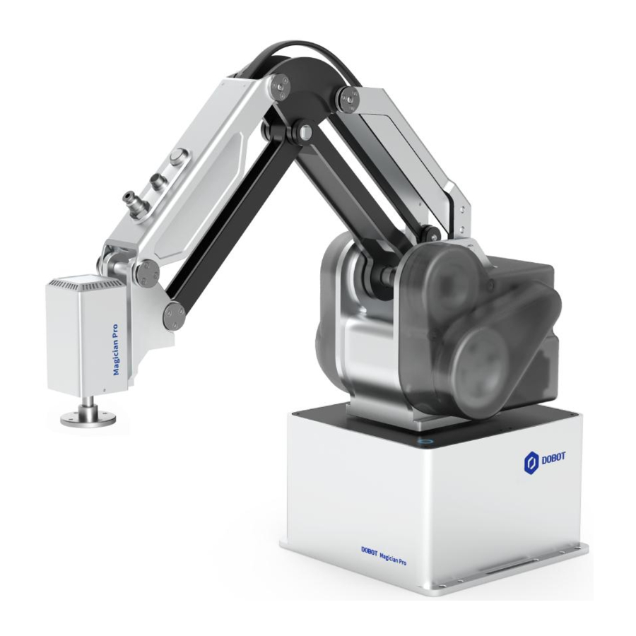
The MG400 training system is an educational solution designed for vocational and higher education to help students understand the functions of standard automation systems and improve the effectiveness of training. A standard MG400 training system is shown in the figure below. The MG400, vision system and air pump box need to be purchased separately.
The MG400 training system can realize the following functions:
- Robot programming and debugging
- User/Tool coordinate system settings
- Palletizing
- Dynamic grasping
- Trajectory programming
- Robot object recognition, etc.
Installation Instructions
The size of MG400 training system is 900×600 mm. The installation position of each part is shown below.

Install MG400
- Remove the four screws from the baseplate for MG400.

- Take the MG400 out of the packing case and place it on the training system, as shown below.

- Secure the MG400 using four screws.

- Connect each cable of the training system to the corresponding interface of the MG400. Connect each cable and air pipe to the corresponding interface of MG400, according to the figures below.


Table 3.1 Description on MG400 interfaces
| Index | Sign | Description |
| A1 | OUT | DO interface |
| A2 | OUT | DO interface |
| B1 | IN | DI interface |
| B2 | IN | DI interface |
| C1 | ENC | Encoder interface, which is used to connect the conveyor belt for dynamic tracking |
| C2 | E-Stop | Emergency stop switch interface |
| Air pipe | AIR | Air source interface. The diameter of the corresponding air pipe is 4mm |
Place toolbox
The MG400 training system is equipped with a toolbox, and the props in the toolbox are used with the MG400 for different operations. The toolbox props are shown below.

Place the toolbox in its corresponding area on the training system for easy access.

Install LED light
The MG400 training system is equipped with an LED status light, including three colors, which is mainly used to display the current operating status of the equipment.
- Place three boat nuts at the installation position of the LED light on the training system, as shown in the figure below.

- Place the LED light on the boat nut.

- Adjust the position of the boat nut based on the hole position of the LED light baseplate.
![warning]() NOTICE
NOTICE
The LED light has four holes, while only three holes are used here.
![]()
- Tighten the three screws and washers with the corresponding boat nuts using the socket head wrench in the toolbox.
![]()


Install vision system
- Install the camera light source kit on the camera, and tighten the 3 fixed knobs on the light source kit to secure it to the camera.

- Assemble the camera support using two M4*10 hexagon socket screws.
![]()
- Fix the camera to the camera support and tighten the screws, as shown below.

- Connect two extension rods together.

- Install the assembled extension rod on the base where the vision system is installed on the training system, and tighten it.

- Install the camera support to the extension rod. It is recommended that the camera support be 2cm away from the top of the extension rod. Adjust the fixture on the camera support to secure the camera support to the extension rod.
![]()
- Connect the I/O cable and USB cable to the camera, as shown in the figure below.

- Disassemble the position as shown in the following figure. Connect the visual light source, and take out the light switch.


Install protective cover
The protective cover can effectively protect the distribution panel of MG400 training system from being squeezed and mis-operated.
- Assemble the three acrylic side-plates of the protective cover using M3*12 flat head screws.

- Assemble the upper cover of the protective cover using M3*12 flat head screws.

- Remove the four screws, as shown in the figure below.

- Place the protective cover to its corresponding position on the training system, and tighten 4 screws.


Install air pump box
- Take the air pump box out of the packing case and place it on the training system.

- Connect the power supply and air pipe to the corresponding interface of the air pump box respectively, as shown in the following figure.


LED Demo
On the MG400 training system, the LED light, namely the LED light buzzer, indicates the operation of each device on the MG400 training system through its color and sound.

I/O description
| DI | Description | DO | Description |
| DI2 | Start | DO6 | Green LED light + green button light |
| DI3 | Stop | DO7 | Yellow LED light + yellow button light |
| DI4 | Reset | DO8 | Red LED light + red button light |
| DI5 | / | DO9 | Buzzer |
Buttons

Import and run project
- Click
![]() in DobotStudio Pro main page to enter Script page. Click File > Import project.
in DobotStudio Pro main page to enter Script page. Click File > Import project.

- Select "script_ LED light buzzer" file folder, and open it.

- Click Save. Enter a project name (such as "LED_light_buzzer') and click OK.
- Click Startto run the program.

 in DobotStudio Pro main page to enter Script page. Click File > Import project.


Demo description
Main program
- Press the green button.
→ The green light is on.
WaitDI(2,1)
DO(6,1) - Press the red button.
→ The green light is off, and the red light is on.
WaitDI(3,1)
DO(6,0)
DO(8,1) - Press the blue button.
→ The red light is off, and the yellow light is on (2s).
→ The yellow light is off, and the green light is on (1s).
→ The green light is off, and the yellow light is on (1s).
→ The yellow light is off, and the red light is on (1s).
→ The green, yellow and red lights are on, and the buzzer rings(2s).
→ The green, yellow and red lights are off, and the buzzer is off (end).
WaitDI(4,1)
DO(8,0)
DO(7,1)
Sleep(2000)
DO(7,0)
DO(6,1) Sleep(1000) DO(6,0)
DO(7,1)
Sleep(1000)
DO(7,0)
DO(8,1)
Sleep(1000)
DO(8,0)
DO(6,1)
DO(7,1)
DO(8,1)
DO(9,1)
Sleep(2000)
DO(6,0)
DO(7,0)
DO(8,0)
DO(9,0)
Trajectory Simulation Demo
In the trajectory simulation demo, the end of the robot can move along the specified trajectory based on the taught points.

Hardware installation
- Install the calibration needle (trajectory needle) on the end of MG400. The red box below shows the parts which need to be assembled.

- Place the trajectory board on the conveyor.


Teach points and run project
- Click
![]() in DobotStudio Pro main page to enter Script page. Click File > Import project.
in DobotStudio Pro main page to enter Script page. Click File > Import project. - Select "script Trajectory" file folder, and open it.
- You need to teach 40 points in this demo. Here shows the points on the trajectory board, which will not be described one by one.

- Click Points, and you will sce 3 points in the point list.

P1 (HOME) is the safe point, as shown below
![]()
- Jog MG400 on the Control panel or drag MG400 to move to gjl point on the calibration board, and cover P2 in the point list.


- Cover P3 (gj2) in the same way.
- Drag MG400 to gj3 point. Click Add on Points panel to add P4.

- Repeat the steps above to teach all the 40 points.
- Click Save, Enter a project name (such as "Trajectory") and click OK.
- Click Startto run the program.
 in DobotStudio Pro main page to enter Script page. Click File > Import project.


Demo description
When the project starts running, the robot will run to the safe point, and then run to gj1 point. After moving a circle along the trajectory, it will return to the safe point. This section does not give detailed description on the script.
Safety Precautions
This section describes the security precautions that should be noticed when you use this product. Please read this document carefully before using the robot for the first time. This product needs to be used in an environment meeting design specification. You cannot remold the product without authorization, otherwise, it could lead to product failure, and even personal injury, electric shock, fire, etc. People who use this product for system design and manufacture must be trained by Yuejiang Technology Co., Ltd., or relevant institutions, or must have the same professional skills, and use the device in strict accordance with the regulations of this document.
Safety warning sign
The following safety warning signs may appear in this document, and their meanings are listed as follows.
| Sign | Description |
| Indicates a high degree of potential danger, which, if not avoided, will result in death or serious injury. |
 ELECTRICITY ELECTRICITY | May cause dangerous power consumption soon, which, if not avoided, will cause personal injury or serious damage to the equipment. |
| HOT | May cause dangerous hot surfaces, if touched, may cause personal injury |
| Indicates a moderate or low potential hazard, which, if not avoided, may cause minor personal injury and damage to the equipment. |
| ATTENTION | Indicates a potential risk, which, if ignored, may result in damage to the robot arm, loss of data or unpredictable results |
| NOTICE | A situation that, if not avoided, can cause personal injury or damage to the equipment. For items marked with such signs, depending on the specific situation, there is sometimes a possibility of significant consequences |
General safety
The following security rules should be followed when you start and use the training system for the first time.
- Ÿ The training system is an electrical device. Non-professional technicians cannot modify the circuit, otherwise, it may cause personal injury or damage to the device. Ÿ You should comply with the local laws and regulations when operating the device.
- The security precautions in this document are only supplemental to the local laws and regulations.
- Ÿ Please use the device in the specified environment scope. Exceeding the specifications or load conditions will shorten the service life of the device, or even damage it.
- Ÿ Please ensure that the device is operated under the security conditions and there is no harmful object around the robot.
- Ÿ Turning on or off the power continually may result in performance degradation of the main circuit components inside the robot. If turning on or off the power continually is required, please keep the frequency less than once a minute.
NOTICE
- Ÿ The personnel responsible for installation, operation and maintenance of equipment must first undergo rigorous training, understand various safety precautions, and master the correct operation and maintenance methods before they can operate and maintain equipment.
- Ÿ Personnel without professional training shall not disassemble and repair the equipment without authorization. If the device fails, please contact Shenzhen Yuejiang Technology Co., Ltd. technical support engineer in time.
- Ÿ Be sure to carry out daily inspections and regular maintenance, and replace faulty components in time to ensure the safe operation of the equipment.
- Ÿ If the equipment is scrapped, please comply with relevant laws to properly handle industrial waste and protect the environment.
- Ÿ In order to prevent personnel from accidentally entering the working space of the robot arm, be sure to set up safety fence to prevent personnel from entering the hazardous area.
- Ÿ Before operating the robot, make sure that no one is inside the safety fence. When operating the robot, be sure to operate outside the safety fence.
- Ÿ Do not expose the training system to permanent magnetic fields all the time. Strong magnetic fields can cause damage to the device.
- Ÿ Shenzhen Yuejiang Technology Co., Ltd. assumes no responsibility for robot damage or personal injury caused by failure to follow product instructions or other improper operations.
- Ÿ Shenzhen Yuejiang Technology Co., Ltd. is not responsible for the damage caused during the transportation and handling of equipment.
- Ÿ Please make sure that the robot is in the packing posture before packaging, and the brakes on each axis are normal.
- Ÿ Before the operation, please wear antistatic uniform and gloves.
- Ÿ It is prohibited to modify or remove the nameplates, instructions, icons, and marks on the equipment.
- Ÿ Be careful during the device carrying or installing. Please follow the instructions on the packing box to put down the device gently and place it correctly in direction of the arrow.
- Ÿ Please carry the robot with both hands. One hand holds the upper arm or forearm and the other hand holds the base, so as to keep the body stable and avoid damage caused by random rotation of the base or loosening of other axes.
- Ÿ For personal security and equipment protection, please use the matched cables.
- Ÿ Please ensure that robot and tools are installed correctly.
- Ÿ Please ensure that the robot has enough space to move freely.
- Ÿ Any impact will release a lot of kinetic energy, with a much more significant effect than that under high speed and high load.
Personal safety
During the operation of the device, it is necessary to ensure the safety of the operator. Please strictly follow the general precautions listed below.
- Ÿ To reduce the risk of personal injury, please comply with local regulations with regard to the maximum weight one person is permitted to carry.
- Ÿ Do not touch the terminal blocks or disassemble the equipment with the power ON. Otherwise, it may result in an electric shock.
- Ÿ Please confirm that the equipment is well grounded, otherwise it will endanger personal safety.
- Ÿ Do not touch the terminal blocks or remove the interval circuit components within 10 minutes after the power is shut off to avoid an electric shock since there is residual capacitance inside the robot.
- Ÿ Even if the power switch of the robot is already in the OFF status, touching the terminal blocks or removing the interval circuit components is not allowed, to avoid an electric shock since there is residual capacitance inside the robot.
- Ÿ Please ensure that safety measures have been established near the operation area, such as guardrails, to protect the operator and surrounding people.
Documents / ResourcesDownload manual
Here you can download full pdf version of manual, it may contain additional safety instructions, warranty information, FCC rules, etc.
Advertisement


Need help?
Do you have a question about the MG400 and is the answer not in the manual?
Questions and answers