Table of Contents
Advertisement
Quick Links
Advertisement
Table of Contents

Related Manuals for Dobot Nova Series


Summary of Contents for Dobot Nova Series
- Page 1 Issue: V1.3 Date: 2023-07-19 Shenzhen Yuejiang Technology CO.,Ltd.|China...
- Page 2 AS IS, which may have flaws, errors or faults. Dobot makes no warranties of any kind, express or implied, including but not limited to, merchantability, satisfaction of quality, fitness for a particular purpose and non-infringement of third party rights.
- Page 3 You can find the model of controller on the right-top corner of the nameplate. Purpose This document introduces the functions, technical specifications and installation procedure of Dobot Nova series robots, which is convenient for users to understand and use the robot. Intended Audience This document is intended for: Issue V1.3 (2023-07-19)
- Page 4 Dobot Nova Series User Guide Customer Sales Engineer Installation and Commissioning Engineer Technical Support Engineer Change History Date Issue Change Description 2023/07/19 V1.3 Update description of tool io Update content styles 2023/02/23 V1.2 Add wiring diagram of emergency stop switch 2023/02/02 V1.1.
-
Page 5: Table Of Contents
Dobot Nova Series User Guide Contents Safety ......................... 1 Liability ..........................1 Validity and Responsibility .................. 1 Limitation of Liability ..................1 Intended Use ......................1 Safety warning signs ......................2 General safety ........................2 Personal security ....................... 5 Emergency ........................6 Emergency stop switch .................. - Page 6 Dobot Nova Series User Guide CCBOX product dimensions ................22 CCBOX horizontal-type installation specifications .......... 22 CCBOX vertical-type installation specifications ..........23 Electrical Features ....................24 CCBOX interface ......................24 Overview ......................24 Robot interface ....................24 Power interface ....................24 Emergency stop switch interface ...............
-
Page 7: Safety
Limitation of Liability Any safety information provided in this document should not be construed as a warranty, by Dobot. The robot may cause injury or damage even if all safety instructions are observed. Intended Use Dobot Nova series robots are commercial robots only for general commercial use, such as processing or delivering food or other products through end tools. -
Page 8: Safety Warning Signs
Dobot Nova Series User Guide • Use over-stated specifications. • Use as a climbing aid. Safety warning signs The following safety warning signs may appear in the products, and their meanings are described as follows. Sign Description Indicates a high degree of potential danger, which, if not avoided, will DANGER result in death or serious injury. - Page 9 Do not expose the robot to permanent magnetic fields all the time. Strong magnetic fields can cause damage to the robot. Dobot assumes no responsibility for robot damage or personal injury caused by failure to follow product instructions or other improper operations. ...
- Page 10 Dobot Nova Series User Guide When the robot is transported, the packaging needs to be fixed to ensure that the robot is stable. After removing the outer packaging, make sure that the robot maintains the original packing posture and the brakes of each axis are normal.
-
Page 11: Personal Security
Dobot Nova Series User Guide WARNING Before the operation, please wear protective clothing, such as antistatic uniform, protective gloves, and protective shoes. It is prohibited to modify or remove the nameplates, instructions, icons and marks on the robot and the related equipment. -
Page 12: Emergency
Dobot Nova Series User Guide Emergency Emergency stop switch After you press the emergency stop switch in emergency, the robot will immediately stop all motions and be locked. According to IEC 60204-1 and ISO 13850, the emergency stop switch is not a safeguard. -
Page 13: Transportation
Ensure that the operator is not unduly stressed on their back or other body parts when lifting the equipment, and use appropriate lifting equipment if necessary. Dobot shall not be held responsible for any damage caused by transportation of the equipment. ... -
Page 14: Product Introduction
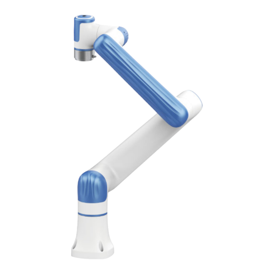
Dobot Nova Series User Guide Product Introduction Overview Figure 3.1 Robot overview The main components of the robot system include: Nova robot: six-axis robot arm, main moving parts. CCBOX: core computing and electrical components. Emergency stop switch: connected to the control cabinet to realize the emergency stop ... -
Page 15: Robot Arm
Figure 3.3 Nova robot arm End button and indicator lights Nova series robot arm is equipped with a button and an indicator light, as shown in Figure 3.4. Figure 3.4 End button and indicator light Issue V1.3 (2023-07-19) User Guide Copyright ©... -
Page 16: Ccbox
CCBOX Nova series robot arms need to be used with a small control cabinet (CCBOX). Figure 3.5 shows the appearance of the CCBOX. For details on its electrical interfaces, see 6 Electrical Features. -
Page 17: Operation Terminal
CCBOX is powered off. Operation terminal Nova series robot arms support control through PC and App, as shown in Table 3.3. If you need to use WiFi for control, you need to plug the WiFi module into the CCBOX. Table 3.2 Operation terminal parameters... -
Page 18: Product Features
Dobot Nova Series User Guide Product Features Coordinate system Joint coordinate system The joint coordinate system is determined based on all motion joints. All joints are rotating joints, as shown in Figure 4.1. Figure 4.1 Joint coordinate system User coordinate system The user coordinate system is a movable coordinate system which is used for representing equipment like fixtures, workbenches. -
Page 19: Tool Coordinate System
Dobot Nova Series User Guide Figure 4.2 User coordinate system Tool coordinate system The tool coordinate system defines the tool center point (TCP) and tool posture, of which the origin and orientations vary with the position and angle of the workpiece at the end of robot. The default tool coordinate system is determined based on the center point of the end flange, as shown in Figure 4.3. -
Page 20: Singularity Point
Dobot Nova Series User Guide degrees. This posture is called the home posture. The home-point stickers as shown in Figure 4.4 are attached to each joint of the robot arm. When the joint is 0 degree, the stickers on both sides of the joint will be aligned. -
Page 21: Elbow Singularity
Dobot Nova Series User Guide Elbow singularity When the upper arm and forearm are in the same line, it will lead to singularity, as shown in Figure 4.6. Figure 4.6 Elbow singularity Wrist singularity When the J4 axis and J6 axis are parallel, it will lead to singularity, as shown in Figure 4.7. -
Page 22: Mechanical Specifications
Dobot Nova Series User Guide Mechanical Specifications All dimensions in this chapter are in millimeters (mm). Nova 2 mechanical specifications Nova 2 dimensions and working space When selecting the installation position for the robot, you must consider the cylindrical space directly over and under the robot, and avoid moving the tool to the cylindrical space as much as possible. -
Page 23: Nova 2 Base
Nova 2 base Figure 5.2 Nova 2 base installation dimensions Nova 2 flange specifications The end flanges of Nova series robot arms are all the same size. The flange design conforms to ISO 9409-1. Figure 5.3 Nova 2 end flange dimensions Issue V1.3 (2023-07-19) -
Page 24: Nova 2 Load Curve
Dobot Nova Series User Guide Nova 2 load curve In the load curve, the coordinate origin is the center of the end flange, and X, Y represent the r = √���� + ���� distance between the gravity center of load and the robot flange in X and Y directions. According to... -
Page 25: Nova 5 Mechanical Specifications
Dobot Nova Series User Guide Nova 5 mechanical specifications Nova 5 dimensions and working space When selecting the installation position for the robot, you must consider the cylindrical space directly over and under the robot, and avoid moving the tool to the cylindrical space as much as possible. -
Page 26: Nova 5 Base Installation Dimensions
Nova 5 base installation dimensions Figure 5.6 Nova 5 base installation dimensions Nova 5 flange dimensions The end flanges of Nova series robot arms are all the same size. The flange design conforms to ISO 9409-1. Figure 5.7 Nova 5 end flange dimensions Issue V1.3 (2023-07-19) -
Page 27: Nova 5 Load Curve
Dobot Nova Series User Guide Nova 5 load curve In the load curve, the coordinate origin is the center of the end flange, and X, Y represent the r = √���� + ���� distance between the gravity center of load and the robot flange in X and Y directions. According to... -
Page 28: Ccbox Dimensions
Dobot Nova Series User Guide CCBOX dimensions CCBOX product dimensions Figure 5.9 CCBOX dimensions CCBOX horizontal-type installation specifications Figure 5.10 Horizontal-type dimensions Issue V1.3 (2023-07-19) User Guide Copyright © Yuejiang Technology Co., Ltd. -
Page 29: Ccbox Vertical-Type Installation Specifications
Dobot Nova Series User Guide CCBOX vertical-type installation specifications Figure 5.11 Vertical-type dimensions Issue V1.3 (2023-07-19) User Guide Copyright © Yuejiang Technology Co., Ltd. -
Page 30: Electrical Features
Dobot Nova Series User Guide Electrical Features CCBOX interface Overview The interfaces of the CCBOX are shown in Figure 6.1. Figure 6.1 CCBOX interfaces Robot interface It is used to connect the robot arm for powering the robot arm and communicating with the robot arm. -
Page 31: Emergency Stop Switch Interface
It is used to connect the emergency stop switch for controlling the emergency stop of the robot arm. Nova series robot arm includes an emergency stop switch in its delivery accessories. The wiring terminals has been connected. You just need to plug it into the corresponding interface. -
Page 32: Analog I/O Interface
Dobot Nova Series User Guide Figure 6.4 Remote switch interface The wiring of connecting external switch is shown in Figure 6.5. Figure 6.5 Remote switch wiring If the switch is turned on for 1 seconds and then disconnected, the CCBOX will be powered on. -
Page 33: Digital I/O Interface
Dobot Nova Series User Guide AI wiring The wiring between the AI interface and the tested object is shown in Figure 6.7. Figure 6.7 AI wiring AO wiring The wiring between the AO interface and the external load is shown in Figure 6.8. -
Page 34: Lan Interface
Dobot Nova Series User Guide DI wiring 1. When you use an external simple circuit as the DI input, the wiring is shown in Figure 6.10. Figure 6.10 DI wiring (simple switch) 2. When you use the 3-wire sensor as the DI input, connect the cables as shown in Figure 6.11. -
Page 35: Usb Interface
Dobot Nova Series User Guide USB interface The CCBOX has two USB interfaces. You can use any of them to connect wireless receiver, and the other can be reserved. Energy feedback resistance interface When the robot arm moves at a fast speed and decelerates for a short time, the overvoltage may occur (the control software will report an overvoltage alarm). - Page 36 24V output DO_2 Digital output 2 DO_1 Digital output 1 The cable used in the tool I/O is specified by Dobot (model: Lutronic FP-222460). The pin distribution and cable definition of the plug are shown as follows. Wire color Description white...
- Page 37 Dobot Nova Series User Guide Figure 6.14 End DI wiring (simple switch) When using the 3-wire sensor as the DI input source, the wiring is shown in Figure 6.15. Figure 6.15 End DI wiring (PNP type DO) The digital output of the tool I/O is NPN type, with the single output current no more than 400mA and the total output current no more than 400mA.
-
Page 38: Installation And Use
Dobot Nova Series User Guide Installation and Use Installation environment To maintain the controller performance and ensure safe use, please place the controller and robot in an environment with the following conditions. NOTICE Please make sure that the installation environment meets the following conditions to avoid damage. -
Page 39: Robot Installation
Dobot Nova Series User Guide Robot installation Robot arm installation Nova robotic arm supports 360° installation at any angle. Figure 7.1 shows several typical installation postures. NOTE The installation posture at the left of the figure is the standard mounting angle. When... -
Page 40: Ccbox Installation
Dobot Nova Series User Guide CCBOX installation The CCBOX supports horizontal-type, vertical-type and rail-type installation. Please leave at least 50 mm gap on each side except the installation surface to ensure enough space for heat dissipation. Horizontal-type After installing the horizontal bracket to the bottom of both sides of the CCBOX, place the CCBOX horizontally on the flat and stable installation surface, and fixed it on the surface with 4 M3*8 screws. -
Page 41: End Tool Installation
Dobot Nova Series User Guide Figure 7.5 Rail-type installation End tool installation The end flange of the robot arm has four M6 threaded holes, which can fix the tool to the end of the robot arm. In order to accurately adjust the position of the tool, you can also use the reserved Φ6 positioning hole. - Page 42 Dobot Nova Series User Guide Figure 7.6 Wiring NOTICE Set the specifications and installation method of external cables in compliance with local power distribution laws and regulations. Do not disassemble the robot by yourself, otherwise it may cause electricity leakage.
-
Page 43: Debugging
CCBOX turn blue, you can connect the robot arm, enable it and jog it for debugging through the operation terminal. For specific operations, refer to DobotStudio Pro User Guide (for PC) or Dobot CRStudio User Guide (for App). -
Page 44: Maintenance
Robots or parts returned to Dobot should be as the following instructions. Remove all parts that do not belong to Dobot. Before returning to Dobot, please make a backup copy of the files. Dobot will not be responsible for the loss of programs, data or files stored in robot. - Page 45 Dobot Nova Series User Guide Table 8.1 Check items Period Maintenance Maintenance essential item Daily 3 months 6 months Wipe off dirt, dust, cutting residue on √ Robot clean the body with water or 10% alcohol Check the torque of exposed bolts √...
- Page 46 In addition, overall maintenance is required every 20,000 hours of operation time or every 4 years (select the shorter of the two periods for maintenance). If you are not clear about the maintenance processes, please contact Dobot technical support. Issue V1.3 (2023-07-19) User Guide Copyright ©...
-
Page 47: Warranty
12 months (15 months at most if the shipping time is included) after the device is put into use, Dobot shall provide the necessary spare part, and the user (customer) shall offer personnel to replace the spare part, using another part that represents the latest technology level to replace or repairing the related part. -
Page 48: Appendix Technical Specifications
Dobot Nova Series User Guide Appendix Technical Specifications Appendix A Robot technical specifications Product Nova 2 Nova 5 Weight 11kg (24.3lb) 14kg (30.9lb) Nominal load 2kg (4.4lb) 5kg (11lb) Working radius 625mm (24.6in) 850mm (33.5in) Maximum working speed 1.6m/s (63in/s) 2m/s (78.7in/s) -
Page 49: Appendix B Ccbox Technical Specifications
Dobot Nova Series User Guide Installation mode Any angle Any angle ① Cable length 3m (118.1 in) 3m (118.1 in) Material acrylonitrile butadiene acrylonitrile butadiene styrene styrene plastic plastic ① cable length between the robot arm and the controller. Appendix B CCBOX technical specifications...
Need help?
Do you have a question about the Nova Series and is the answer not in the manual?
Questions and answers