Dobot Magician User Manual
Hide thumbs
Also See for Magician:
- User manual (253 pages) ,
- User manual instruction and precautions (167 pages) ,
- User manual (116 pages)

Related Manuals for Dobot Magician


Summary of Contents for Dobot Magician
- Page 1 User Guide Dobot Magician User Guide (DobotLab-based) Issue: V2.0 Date: 2022-05-27 Shenzhen Yuejiang Technology Co., Ltd.
- Page 2 Even if follow this document or any other related instructions, damages or losses may happen in the using process. Dobot shall not be considered as a guarantee regarding to all security information contained in this document.
- Page 3 Dobot Magician User Guide (DobotLab-based) Preface Preface Purpose This document describes the working principle, technical specifications, connection and functions of Dobot Magician, making it easy for u sers to fully understand and use it. Intended Audience This document is intended for: Customer Engineer ...
-
Page 4: Table Of Contents
Technical Specifications ....................9 Technical Parameters ................... 9 Dimensions ......................10 Robot Connection ....................12 Connecting Cables to Dobot Magician ................12 Powering on/off Dobot Magician ................... 12 Interface Description ..................... 14 Interface Board ....................... 14 LED Indicator ......................... 15 Multiplexed I/O Interface .................... - Page 5 Dobot Magician User Guide (DobotLab-based) Contents Installing 3D Printing Kit .................. 68 Burning Firmware ..................... 72 Operating Repetier Host ..................73 Operating Cura ....................85 Calibration ........................90 Base Calibration ....................90 Sensor Calibration ..................... 95 Homing ......................102 Working in Offline Mode ....................104 Operating Stick Controller Kit ..................
-
Page 6: Security Precautions
People cannot repair and disassemble the robotic arm without professional training. If there is a problem with the robotic arm, please contact Dobot technical support engineer in time. Please comply with the relevant laws to deal with the product which is scrapped, and protect the environment. -
Page 7: Precautions
LED indicator completely turns off, the Dobot Magician can be powered down. If the coordinates of the Dobot Magician shown on DobotLab are abnormal, please press the Reset button on the back of the base to reset Dobot Magician or click Home on DobotLab to perform homing. ... - Page 8 The heating rod will produce high temperature up to 250℃ when you use the 3D printing module. Please be careful. Please DO NOT operate or turn off Dobot Magician when burning firmware, to avoid machine damage. Issue V2.0 (2022-05-27) User Guide Copyright ©...
-
Page 9: Introduction
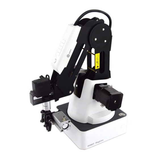
3D printing, etc. It also supports secondary development by various extensible I/O interfaces. Appearance Dobot Magician consists of a base, rear arm, forearm, and end-effector, etc. Figure 2.1 shows the appearance. Figure 2.1 Appearance of Dobot Magician Working Principle This section describes the workspace, principle, size and technical specifications of Dobot Magician. - Page 10 Dobot Magician User Guide (DobotLab-based) Figure 2.2 Workspace of Dobot Magician (1) Figure 2.3 Workspace of Dobot Magician (2) Issue V2.0 (2022-05-27) User Guide Copyright © Yuejiang Technology Co., Ltd.
-
Page 11: Coordinate System
Dobot Magician User Guide (DobotLab-based) Coordinate System Dobot Magician has two types of coordinate system, the joint one and the Cartesian one, as shown in Figure 2.4 and Figure 2.5 respectively. Figure 2.4 Joint coordinate system Figure 2.5 Cartesian coordinate system Joint coordinate system: The coordinates are determined by motion joints. -
Page 12: Motion Function
Joint coordinate system when teaching. Cartesian coordinate system mode Click X+, X- and Dobot Magician will move along X-axis in the negative or positive direction. Click Y+, Y- and Dobot Magician will move along Y-axis in the negative or positive direction. - Page 13 Dobot Magician User Guide (DobotLab-based) MOVJ: Joint movement. From point A to point B, each joint runs from initial angle to its target angle, regardless of the trajectory, as shown in Figure 2.6. Figure 2.6 MOVL & MOVJ mode ...
-
Page 14: Technical Specifications
Dobot Magician User Guide (DobotLab-based) Figure 2.8 ARC mode 2.3.3.4 Application Scenarios The application scenario depends on the trajectory in a motion mode, as shown in Table 2.1. Table 2.1 Application scenario Motion mode Application scenario MOVL If the trajectory of playback is required as a straight line, you can choose MOVL... -
Page 15: Dimensions
Software DobotLab Working temperature -10°C~60°C Dimensions Figure 2.9 shows the size of Dobot Magician and Figure 2.10 shows the size of the end mounting hole. Figure 2.9 Size of Dobot Magician Issue V2.0 (2022-05-27) User Guide Copyright © Yuejiang Technology Co., Ltd. - Page 16 Dobot Magician User Guide (DobotLab-based) Figure 2.10 Size of end mounting hole Issue V2.0 (2022-05-27) User Guide Copyright © Yuejiang Technology Co., Ltd.
-
Page 17: Robot Connection
LED indicator turns from yellow to green. Now the Dobot Magician is powered on. NOTICE If the LED indicator is red after the Dobot Magician is powered on, it means that the robotic arm reaches its limited position. To return to the workspace, press and hold the unlock button on the forearm to move the robotic arm to another desired position. - Page 18 Dobot Magician User Guide (DobotLab-based) Figure 3.2 Gesture of Dobot Magician before power-on Power off: When the LED indicator is green, press down the power button to turn off the robotic arm. In this case, the forearm moves slowly to the rear arm while the angle between them becomes small.
-
Page 19: Interface Description
Dobot Magician User Guide (DobotLab-based) Interface Description Interface Board The interfaces of Dobot Magician are located on the back of the base and the forearm respectively. Figure 4.1 shows the interfaces on the back of the base, and Table 4.1 lists the description. -
Page 20: Led Indicator
Dobot Magician User Guide (DobotLab-based) Table 4.2 Peripheral interface description Interface Description Power interface of air pump; output 12V of controllable power Output 12V of controllable power Stepper1 User-defined stepper interface; extruder interface (3D printing mode) Stepper2 User-defined stepper interface Signal interface of air pump;... -
Page 21: Multiplexed I/O Interface
Connection of 3D printing kit is abnormal Multiplexed I/O Interface The addresses of the I/O interfaces in Dobot Magician are unified. Most of I/O interfaces have multiple functions. You can obtain the level output and input through I/O interfaces to control the peripheral equipment. - Page 22 Dobot Magician User Guide (DobotLab-based) Table 4.5 Multiplex I/O Description Whether pull up Description Level output Level input or pull down 5V/1A output Ground 3.3V_20mA E2 (EIO18) No pulling output 3.3V/5V_20mA Pull up 1M to E1 (EIO19) input 3.3V 3.3V_20mA...
- Page 23 Dobot Magician User Guide (DobotLab-based) Table 4.6 Multiplexed I/O Description Whether pull Level Level Interface Description up or pull output input down VALVE 12V/1A (EIO16) output Ground PUMP 12V/1A (EIO17) output Ground 5_1A 5_1B Default Stepper1 phase 5_2A voltage and...
-
Page 24: Multiplexed Forearm I/O Interface Description
Dobot Magician User Guide (DobotLab-based) Whether pull Level Level Interface Description up or pull output input down 3.3V/5V_ 3.3V_20mA Pull up 1M to √ 10mA output 3.3V (EIO14) input 5V/1A output (EIO13) Ground Multiplexed Forearm I/O Interface Description Figure 4.5 shows the peripheral interface on the forearm, Table 4.7 lists the multiplexed I/O description. - Page 25 Dobot Magician User Guide (DobotLab-based) Whether Level Level Interface Description pull up or output input pull down (EIO1) to 3.3V Ground FAN_12V 12V/1A Fan power (EIO2) output Ground HEAT_12V Heating- 12V/3A (EIO3) wire power output Ground Ground 3.3V/5V Pull up 1M to _20mA 3.3V...
-
Page 26: Internal I/O Circuit
Dobot Magician User Guide (DobotLab-based) Whether Level Level Interface Description pull up or output input pull down mode. 3.3V_20m √ No pulling (EIO8) output 5V/1A output Ground Internal I/O Circuit Pull up 1M to 3.3V Figure 4.6 Pull up 1M to 3.3V 3.3V Pull up 10K to 3.3V... -
Page 27: Example Of External Device Connection
Dobot Magician User Guide (DobotLab-based) Pull down 1M to ground Figure 4.8 Pull down 1M to ground No pulling Figure 4.9 No pulling Example of External Device Connection This section takes air-pump connection as an example to illustrate the external device connection. - Page 28 Dobot Magician User Guide (DobotLab-based) Figure 4.10 Example of external device connection Issue V2.0 (2022-05-27) User Guide Copyright © Yuejiang Technology Co., Ltd.
-
Page 29: Operation
Operation Introduction on DobotLab Dobot Magician has multiple functions including teaching and playback, writing and drawing, blockly programming, script control, etc., which can be realized through DobotLab, an integrated software platform specially designed for artificial intelligence (AI) education. You can enter DobotLab through https://dobotlab.dobot.cc/. -
Page 30: Dobotlink Installation
Laser Engraving Lab Engrave a bitmap image using a laser Teaching and Playback Lab Teach the Dobot Magician how to move and then record the movement to make Dobot Magician accomplish the recorded movements 3D Printing Lab Control the Dobot Magician for 3D printing... -
Page 31: Blockly
Blockly DobotBlock Lab is specially designed for beginners in programming. You can program by dragging blocks to control the movement of Dobot Magician. Prerequisites Dobot Magician has been powered on, and connected to DobotLab. Procedure Issue V2.0 (2022-05-27) User Guide... - Page 32 Dobot Magician User Guide (DobotLab-based) Figure 5.6 Choose device Figure 5.7 Add an extension Issue V2.0 (2022-05-27) User Guide Copyright © Yuejiang Technology Co., Ltd.
- Page 33 Dobot Magician User Guide (DobotLab-based) Figure 5.8 Connect device Figure 5.9 Device connected • Set parameters corresponding to each block based on actual requirements. • The program written with blocks requires triggering conditions to run. Therefore, you need to select a command from the event block as the triggering condition.
- Page 34 Dobot Magician User Guide (DobotLab-based) Figure 5.10 Blockly programming If you need to set sprites and stages in the program, follow Step 7~ Step 10. Issue V2.0 (2022-05-27) User Guide Copyright © Yuejiang Technology Co., Ltd.
- Page 35 Dobot Magician User Guide (DobotLab-based) Figure 5.11 Sprite list Figure 5.12 Sprite extension kit Issue V2.0 (2022-05-27) User Guide Copyright © Yuejiang Technology Co., Ltd.
-
Page 36: Python Programming
You can control Dobot Magician through script. Dobot Magician supports various APIs, such as velocity/acceleration setting, motion mode setting, and I/O configuration, which uses Python language for secondary development. For details about the Dotot Magician API interface and their functions, see Dobot Magician API Description. - Page 37 Dobot Magician User Guide (DobotLab-based) Figure 5.15 Python main page Table 5.2 Python Lab main interface Function Description Program control : Start to run the program in the code area : Download the current program in the code area to the...
- Page 38 Code area Area for writing programs Running log Display running process Prerequisites Dobot Magician has been powered on and connected to DobotLab. Procedure Figure 5.16 Connect device Figure 5.17 Device connected Issue V2.0 (2022-05-27) User Guide...
-
Page 39: Writing And Drawing
Figure 5.18 Write Python programs Figure 5.19 Save the project NOTE The script can be downloaded from DobotLab to Magician only in wired control mode. Writing and Drawing Figure 5.20 shows the process of writing and drawing. Issue V2.0 (2022-05-27) User Guide Copyright ©... -
Page 40: Installing A Writing And Drawing Kit
Dobot Magician User Guide (DobotLab-based) Figure 5.20 The process of writing and draw Installing a Writing and Drawing Kit A writing and drawing kit consists of a pen and a pen holder. The specific installation steps are shown below. Figure 5.21 Install a writing and drawing kit Issue V2.0 (2022-05-27) -
Page 41: Drawing Operations (Without Sliding Rail)
Dobot Magician User Guide (DobotLab-based) NOTE To change a new pen, unfasten the four M3*5 set screws in the pen holder with a 1.5mm hexagon wrench, as shown in Figure 5.22. Figure 5.22 Change to a new pen Drawing Operations (Without Sliding Rail) 5.5.2.1 Connecting DobotLab... - Page 42 Dobot Magician User Guide (DobotLab-based) Figure 5.24 Device connected 5.5.2.2 Importing Image Files and Setting Writing Parameters Before the Magician starts to write and draw, you need to import an image or enter characters as the target model. Figure 5.25 Add text NOTE...
- Page 43 Dobot Magician User Guide (DobotLab-based) Figure 5.26 Image beyond bound Figure 5.27 Set pen lifting height, descent height and speed NOTE Generally, you can set the pen lifting height and descent height to 20 by default. NOTE Issue V2.0 (2022-05-27) User Guide Copyright ©...
- Page 44 Dobot Magician User Guide (DobotLab-based) If you do not click Synchronize before running, the image can also be drawn normally. After you click Run, the robot arm moves directly over the starting point to draw. 5.5.2.3 Drawing Figure 5.28 Drawing progress Figure 5.29 Save the project...
-
Page 45: Installing A Sliding Rail Kit
Figure 5.30 Download the file Installing a Sliding Rail Kit When the workspace of Dobot Magician is not enough, you can extend the space with a sliding kit, so as to realize such tasks as long-distance picking, writing couplets and so on. - Page 46 Dobot Magician User Guide (DobotLab-based) Figure 5.31 Fix plate a Figure 5.32 Fix Magician Issue V2.0 (2022-05-27) User Guide Copyright © Yuejiang Technology Co., Ltd.
- Page 47 Dobot Magician User Guide (DobotLab-based) Figure 5.33 Connect to wire set Figure 5.34 Connect to Dobot Magician Issue V2.0 (2022-05-27) User Guide Copyright © Yuejiang Technology Co., Ltd.
-
Page 48: Drawing Operations (With A Sliding Rail)
Drawing Operations (with a Sliding Rail) This section describes how to use a sliding rail for writing. Prerequisites The sliding rail kit has been installed and connected to the Dobot Magician. Dobot Magician has been powered on and connected to DobotLab successfully. ... - Page 49 Dobot Magician User Guide (DobotLab-based) Figure 5.37 Connect device Figure 5.38 Device connected 5.5.4.2 Connecting Sliding Rail Issue V2.0 (2022-05-27) User Guide Copyright © Yuejiang Technology Co., Ltd.
- Page 50 Dobot Magician User Guide (DobotLab-based) Figure 5.39 Enable sliding rail Issue V2.0 (2022-05-27) User Guide Copyright © Yuejiang Technology Co., Ltd.
- Page 51 Dobot Magician User Guide (DobotLab-based) Figure 5.40 Drawing area (sliding rail connected) NOTICE Before you click Home, please take the pen off or raise the Dobot Magician arm up. 5.5.4.3 Importing Image/Text and Setting Parameters Issue V2.0 (2022-05-27) User Guide...
- Page 52 If you want to write the text in a certain order, you need to import an image with a defined point order. If you enter the text through Add Text, the Magician will write the text overall from left to right.
- Page 53 If you want to set an action to dip the pen into the ink, you can press Unlock key and drag the Dobot Magician to a point, and then release to get this point position on the command area. For details, refer to the steps below.
- Page 54 Dobot Magician User Guide (DobotLab-based) shown in Figure 5.44. Figure 5.44 Add trigger line A blue trigger line appears in the drawing area. Move the trigger line to a proper position, as shown in Figure 5.45. Figure 5.45 Move trigger line...
- Page 55 Unlock key to record the first point. as shown in Figure 5.47. Figure 5.47 Save the first point NOTICE Make this point higher within the Dobot Magician workplace to prevent the writing brush from touching the inkstone. Move the forearm to the inkstone positions shown in Figure 5.48, and record these points on the “Trigger Trajectory”...
- Page 56 Dobot Magician User Guide (DobotLab-based) Figure 5.48 Simulate the actions of ink dipping Drag the forearm to raise the writing brush up, for avoiding touching the inkstone. NOTICE As the inkstone has its own height, you need to set a suitable rising height to prevent the writing brush from touching the inkstone.
-
Page 57: Laser Engraving
Dobot Magician User Guide (DobotLab-based) Figure 5.49 Start writing text Figure 5.50 Save the file Laser Engraving Figure 5.51 shows the process of laser engraving. Issue V2.0 (2022-05-27) User Guide Copyright © Yuejiang Technology Co., Ltd. -
Page 58: Installing A Laser Kit
Dobot Magician User Guide (DobotLab-based) Figure 5.51 Process of laser engraving Installing a Laser Kit Procedure A laser kit includes a laser. The installation steps are described as below. Issue V2.0 (2022-05-27) User Guide Copyright © Yuejiang Technology Co., Ltd. -
Page 59: Laser Engraving Operations
Dobot Magician User Guide (DobotLab-based) Figure 5.52 Fasten the laser with clamp fixing screw Laser Engraving Operations 5.6.2.1 Connecting DobotLab Figure 5.53 Connect device Issue V2.0 (2022-05-27) User Guide Copyright © Yuejiang Technology Co., Ltd. - Page 60 Dobot Magician User Guide (DobotLab-based) Figure 5.54 Device connected 5.6.2.2 Importing Image Files and Setting Engraving Parameters Figure 5.55 NOTE The image in the drawing area should be placed within the annular area. If not, the robotic arm reaches its limited position and cannot engrave. In this case, the image is highlighted with a red border, as shown below.
- Page 61 Dobot Magician User Guide (DobotLab-based) Figure 5.56 Image beyond bound Issue V2.0 (2022-05-27) User Guide Copyright © Yuejiang Technology Co., Ltd.
- Page 62 Never aim the laser at a person and their clothes. Do not allow the children to play with the Dobot Magician. Monitor the robotic arm while it is running and power off it once the movement is complete. Issue V2.0 (2022-05-27) User Guide Copyright ©...
- Page 63 Dobot Magician User Guide (DobotLab-based) NOTICE If you cannot set the laser to be at its minimum focus, it’s probably because the focal length is long. To shorten the focal length, slightly turn the screw (as shown inFigure 5.58) on the bottom of the laser kit.
-
Page 64: Teaching And Playback
This section introduces how to perform a teaching & playback task to suck or grab a small object. Installing a Suction Cup Kit A suction cup kit is the default end-effector shipped with the Dobot Magician. When you use the suction cup kit, an air pump is necessary, as shown in Figure 5.61. Issue V2.0 (2022-05-27) User Guide Copyright ©... -
Page 65: Installing A Gripper Kit
Dobot Magician User Guide (DobotLab-based) Figure 5.61 A suction cup kit Procedure Please install a suction cup kit based on Figure 5.62. Figure 5.62 Connect the air pump to the Dobot Magician Installing a Gripper Kit Issue V2.0 (2022-05-27) User Guide... - Page 66 Dobot Magician User Guide (DobotLab-based) An air pump should be used with the gripper kit, as shown in Figure 5.63, to open or close the gripper. Figure 5.63 Gripper kit Procedure Figure 5.64 Dismantle the suction cup Issue V2.0 (2022-05-27) User Guide Copyright ©...
-
Page 67: Teaching And Playback
Dobot Magician User Guide (DobotLab-based) Figure 5.65 Install a gripper kit Figure 5.66 Effect of the gripper kit installation Teaching and Playback The main interface of Teaching and Playback Lab is shown in Figure 5.67, and the specific description is listed in Table 5.3. - Page 68 Dobot Magician User Guide (DobotLab-based) Figure 5.67 Teaching and Playback Lab interface Table 5.3 Description on Teaching and Playback Lab Modules Description Program control Start running Operation settings Settings: Set speed and acceleration Command panel: Set motion mode, pause time, end-effector, lost step detection, I/O trigger, and save point.
- Page 69 Dobot Magician User Guide (DobotLab-based) Modules Description Project name Display the name of the current project Device connection Select the target device and establish a communication connection with the device Arm control panel Control Dobot Magician Command area Display added commands. You can right-click a command to copy,...
- Page 70 Dobot Magician User Guide (DobotLab-based) Figure 5.70 Save points Figure 5.71 Jump parameter setting Issue V2.0 (2022-05-27) User Guide Copyright © Yuejiang Technology Co., Ltd.
- Page 71 Any two points cannot coincide. The three points cannot be in the same straight line. The arc trajectory cannot exceed the Dobot Magician’s normal workspace. Issue V2.0 (2022-05-27) User Guide Copyright © Yuejiang Technology Co., Ltd.
-
Page 72: 3D Printing
Dobot Magician User Guide (DobotLab-based) Figure 5.74 Save the project 3D Printing After installing an 3D printing kit, you can import 3D module into the 3D printing software to perform 3D printing. Figure 5.75 shows the 3D printing process. Issue V2.0 (2022-05-27) User Guide Copyright ©... -
Page 73: Installing 3D Printing Kit
Dobot Magician User Guide (DobotLab-based) Figure 5.75 3D printing process During 3D printing, the 3D printing control software is required. You can use Repetier Host or Cura software for 3D printing. Reptier-Host: Reptier-Host can slice with the third party slicing (such as CuraEngine, Slic3r, etc), check and modify G-Code, control 3D printing manually. - Page 74 Dobot Magician User Guide (DobotLab-based) Figure 5.76 3D printing kit Procedure Issue V2.0 (2022-05-27) User Guide Copyright © Yuejiang Technology Co., Ltd.
- Page 75 Dobot Magician User Guide (DobotLab-based) Figure 5.77 Push down the filament Figure 5.78 Connect extruder and hot end NOTICE Please make sure that the PTFE tube has been pushed down to the bottom of the hot end. Otherwise, it will cause abnormal discharge.
- Page 76 Dobot Magician User Guide (DobotLab-based) Figure 5.79 Fix hot end Figure 5.80 Connect hot end to the Forearm Issue V2.0 (2022-05-27) User Guide Copyright © Yuejiang Technology Co., Ltd.
-
Page 77: Burning Firmware
Dobot Magician User Guide (DobotLab-based) Figure 5.81 Connect with extruder Figure 5.82 Place filament and extruder to the Filament holder Burning Firmware Procedure Click on DobotLab main page, and you will see the following pop-up window. If the 3D printing firmware has been burned, you can directly open the 3D printing software to use it. -
Page 78: Operating Repetier Host
Upgrade page, and click Connect. After selecting the firmware type, click Start Upgrading. Figure 5.84 Burn firmware WARNING Please DO NOT operate or turn off Dobot Magician when burning firmware, to avoid machine damage. If the coordinates are abnormal after burning firmware, please reboot Dobot Magician. - Page 79 Dobot Magician User Guide (DobotLab-based) The printing platform has been prepared and please place it in the workspace of the Dobot Magician. Dobot Magician has been powered on and connected to DobotLab successfully (Only USB connection is supported).
- Page 80 Dobot Magician User Guide (DobotLab-based) Figure 5.86 Unselect options Set the corresponding parameters on the Extruder tab as shown in the red box of Figure 5.87, and the other parameters are set by default. Then click Apply. Issue V2.0 (2022-05-27) User Guide Copyright ©...
- Page 81 Dobot Magician User Guide (DobotLab-based) Figure 5.87 Extruder settings Set the corresponding parameters on the Printer Shape tab as shown in the red box of Figure 5.88, and the other parameters are set by default. Then click Apply. Issue V2.0 (2022-05-27) User Guide Copyright ©...
- Page 82 After the connection is successful, the current heating temperature will be shown on the below of the Repetier Host page, as shown in Figure 5.89. Figure 5.89 Connect to Dobot Magician Before printing, you need to test the extruder to check whether the melted filament flows from the nozzle of the extruder.
- Page 83 Dobot Magician User Guide (DobotLab-based) The temperature of the extruder should be above 170℃. Dobot Magician will not start 3D printing until the filament is in the melting state. So you need to heat the extruder first. Set the heating temperature to 200℃ on the Manual Control tab of the Repetier Host page and click , as shown in Figure 5.90.
- Page 84 NOTE During printing, if the distance from Dobot Magician to the printing platform is too large or too small to paste the first layer, it can lead to the nozzle blockage. For increasing the stickiness of the first layer, placing a masking paper on the platform is recommended.
- Page 85 Dobot Magician User Guide (DobotLab-based) coordinates. Figure 5.92 Input M415 NOTE If you cannot find the G-Code command window, please click EASY to close Easy Mode, as shown in Figure 5.93. Figure 5.93 Easy mode Issue V2.0 (2022-05-27) User Guide...
- Page 86 Dobot Magician User Guide (DobotLab-based) Figure 5.94 Import 3D printing model After importing the model, you can center, zoom, or rotate the model on the Object Placement page, as shown in Figure 5.95. Figure 5.95 Model operation You need to set the slicing parameters before first printing.
- Page 87 Dobot Magician User Guide (DobotLab-based) Figure 5.96 Select slicer The Slic3r page is displayed, as shown in Figure 5.97. Figure 5.97 Slic3r page Set the slicing parameters on the Slic3r page. The 3D printing effect depends on the slice parameters. This topic provides a Issue V2.0 (2022-05-27)
- Page 88 File > Load Config on the Slic3r page to import it directly for printing. Figure 5.98 Configuration sample Dobot-2.0-Vase.ini is used for printing a thin-walled vase, while Dobot-2.0-ini is used for the filling, the filling rate is 20%. Save the Printing Settings, Filament Settings and Printer Settings tabs respectively after importing configuration sample, as shown in Figure 5.99.
- Page 89 Dobot Magician User Guide (DobotLab-based) Figure 5.100 Start to slice Click on the top left corner of the Repetier Host page to print. Figure 5.101 Start printing Here the vase mode is adopted to print, and the product after printing is shown in Figure 5.102.
-
Page 90: Operating Cura
The 3D printing model has been prepared. The printing platform has been prepared and placed within the workspace of Dobot Magician. Dobot Magician has been powered on, and connected to DobotLab successfully (Only USB connection is supported). - Page 91 Dobot Magician User Guide (DobotLab-based) shown in Figure 5.103. Table 5.4 lists the values of the parameters that need to be set. The other parameters are set by default. Figure 5.103 Parameters setting Table 5.4 3D printing parameters description Parameter...
- Page 92 The 3D printing effect depends on the slice parameters. This topic provides a configuration sample, you can import it directly for printing. Figure 5.105 Configuration sample Dobot-2.0-Vase-Cura.ini is used for printing a thin-walled vase, while Dobot-2.0- Cura.ini is used for the filling, the filling rate is 20%. Click , the Open 3D model page is displayed, and select the 3D printing model prepared.
- Page 93 Set Temperature to 200 and press down Enter to heat the extruder. The temperature of the extruder should be above 170℃. Dobot Maigicain will not start 3D printing until the filament is in the melting state. So you need to heat the extruder first.
- Page 94 NOTE During printing, if the distance from Dobot Magician to the printing platform is too large or too small to paste the first layer, it can lead to the nozzle blockage. For increasing the stickiness of the first layer, placing a masking paper on the platform is recommended.
-
Page 95: Calibration
The writing and drawing kit has been installed. For details, see 5.5.1 Installing a Writing and Drawing Kit. Dobot Magician has been powered on, and connected to DobotLab. DobotLink has been started. The sensor calibration board has been prepared. - Page 96 Click the drop-down list of device connection panel, as shown below. Choose Magician and click Connect. Press the Unlock key on the Forearm and drag Dobot Magician to make the nib contact the surface of the calibration board, then release the Unlock key. The coordinates of this point will be displayed on the command area.
- Page 97 Dobot Magician User Guide (DobotLab-based) Figure 5.111 Enter machine calibration Figure 5.112 Connect device Issue V2.0 (2022-05-27) User Guide Copyright © Yuejiang Technology Co., Ltd.
- Page 98 Dobot Magician User Guide (DobotLab-based) Figure 5.113 Base calibration Dobot will start homing. Please ensure that there are no obstacles within the workspace during homing. If the speed is too fast when moving J1-axis, you can drag speed slider to adjust speed.
- Page 99 Dobot Magician User Guide (DobotLab-based) Figure 5.114 Adjust J1 axis Figure 5.115 Nib position You can check the J1-coordinate on the Arm Control Panel page, as shown in Figure 5.116. Issue V2.0 (2022-05-27) User Guide Copyright © Yuejiang Technology Co., Ltd.
-
Page 100: Sensor Calibration
The angle sensors of the Forearm and Rear Arm have been calibrated before being shipped out. Generally, the Z-coordinate will remain the same when moving Dobot Magician in the same horizontal plane. If changed, you need to recalibrate the angle sensors by manual levelling or auto levelling to improve the positioning accuracy. - Page 101 Dobot Magician User Guide (DobotLab-based) Figure 5.117 Location of Dobot Magician Figure 5.118 Connect device The Manual Levelling page is displayed. NOTICE Please remove all end-effectors from Dobot Magician before calibrating Issue V2.0 (2022-05-27) User Guide Copyright © Yuejiang Technology Co., Ltd.
- Page 102 Dobot Magician User Guide (DobotLab-based) Figure 5.119 Adjust the first calibrated point Figure 5.120 Move to the first calibrated point Issue V2.0 (2022-05-27) User Guide Copyright © Yuejiang Technology Co., Ltd.
- Page 103 Dobot Magician User Guide (DobotLab-based) Figure 5.121 Adjust the second calibrated point Figure 5.122 Move to the second calibrated point Issue V2.0 (2022-05-27) User Guide Copyright © Yuejiang Technology Co., Ltd.
- Page 104 Figure 5.123 Set the distance between two calibrated points NOTICE Please DO NOT drag Dobot Magician in this step, to avoid manual levelling failure. If the speed is too fast when clicking coordinate buttons, you can drag the speed slider to adjust the speed.
- Page 105 Dobot Magician User Guide (DobotLab-based) Figure 5.124 Auto-levelling tool Procedure NOTICE Please ensure that the platform is flat. Otherwise, the auto levelling will be failed. Figure 5.125 Fix auto-levelling tool Issue V2.0 (2022-05-27) User Guide Copyright © Yuejiang Technology Co., Ltd.
- Page 106 Dobot Magician User Guide (DobotLab-based) Figure 5.126 Insert the cable of the auto-levelling Issue V2.0 (2022-05-27) User Guide Copyright © Yuejiang Technology Co., Ltd.
-
Page 107: Homing
Dobot Magician User Guide (DobotLab-based) Figure 5.127 Automatic leveling NOTICE Please ensure that there are no obstacles in the workspace during auto levelling. Figure 5.128 Start automatic leveling Homing Issue V2.0 (2022-05-27) User Guide Copyright © Yuejiang Technology Co., Ltd. - Page 108 Dobot Magician User Guide (DobotLab-based) Dobot Magician has been calibrated before being shipped out. If the Dobot Magician has been hit or the motor has lost step, you need to operate homing to improve the positioning accuracy. Prerequisites Dobot Magician has been powered on, and connected to DobotLab.
-
Page 109: Working In Offline Mode
Dobot Magician User Guide (DobotLab-based) Figure 5.130 Set home position Working in Offline Mode Offline mode allows the Dobot Magician to perform the points in the Save points list previously downloaded from DobotLab, without keeping the USB connection established. Prerequisites •... -
Page 110: Operating Stick Controller Kit
Figure 5.132 Base panel Operating Stick Controller Kit Dobot Magician can be controlled by stick controller kit. As shown in Figure 5.133, the stick controller kit includes (from left to right) a stick controller, a USB Host module, a USB cable (used Issue V2.0 (2022-05-27) - Page 111 Figure 5.133 Stick controller kit NOTICE Please do not connect Dobot Magician to DobotLab when operating the stick controller. Please turn off the Dobot Magician completely first before connecting or disconnecting external equipment. Otherwise, it causes serious damage to your device.
- Page 112 Dobot Magician User Guide (DobotLab-based) Figure 5.134 Connect with USB Host module The red LED indicator on the middle of the stick controller is on, indicating that the Dobot Magician can be controlled by the stick controller. Issue V2.0 (2022-05-27) User Guide...
- Page 113 Control the intake of the air pump Turn off the air pump Left stick: Front/back Cartesian coordinate system mode: Dobot Magician moves along X-axis in the positive/negative direction Joint coordinate system mode: Dobot Magician rotates along J1-axis in the positive/negative direction Issue V2.0 (2022-05-27)
-
Page 114: Multiplexed I/O Demo
J4-axis in the positive/negative direction Multiplexed I/O Demo The addresses of the I/O interfaces in Dobot Magician are unified. Most of I/O interfaces have multiple functions. For details, see 4.3 Multiplexed I/O Interface. You can set I/O interfaces in the command panel of Teaching and Playback Lab, as shown in Figure 5.136;... - Page 115 Dobot Magician User Guide (DobotLab-based) Figure 5.136 IO settings in Teaching and Playback Lab Issue V2.0 (2022-05-27) User Guide Copyright © Yuejiang Technology Co., Ltd.
-
Page 116: Level Output
Dobot Magician User Guide (DobotLab-based) Figure 5.137 IO settings in DobotBlock Lab Figure 5.138 IO settings in Python Lab This section takes Teaching and Playback Lab as an example to illustrate level output, level input, and PWM output. Level Output Normally, an air pump can be controlled by the I/O interfaces. - Page 117 5.139. Figure 5.139 Peripheral Interface on the base Prerequisites • The air pump has been connected to Dobot Magician. For details, see “5.7.1 Installing a Suction Cup Kit”. • Dobot Magician has been powered on, and connected to DobotLab successfully.
- Page 118 Dobot Magician User Guide (DobotLab-based) Figure 5.140 Set end-effector Figure 5.141 Trigger commands Issue V2.0 (2022-05-27) User Guide Copyright © Yuejiang Technology Co., Ltd.
-
Page 119: Level Input
Level Output Level Input √ 3.3V Prerequisites Dobot Magician has been powered on, and connected to DoboLab successfully. The saved points list has been existed in the Teaching and Playback Lab. Procedure Issue V2.0 (2022-05-27) User Guide Copyright © Yuejiang Technology Co., Ltd. -
Page 120: Pwm Output
Dobot Magician User Guide (DobotLab-based) Figure 5.143 Add IO trigger command Figure 5.144 Move the trigger command PWM Output This section also takes I/O 11 as an example. Table 5.8 Multiplexed I/O description I/O addressing Voltage Level Output Level Input √... - Page 121 Dobot Magician User Guide (DobotLab-based) Prerequisites Dobot Magician has been powered on, and connected to DobotLab successfully. Procedure Figure 5.145 Add IO trigger command Figure 5.146 Move the trigger command Issue V2.0 (2022-05-27) User Guide Copyright © Yuejiang Technology Co., Ltd.
Need help?
Do you have a question about the Magician and is the answer not in the manual?
Questions and answers