Dobot MG400 User Manual
Hide thumbs
Also See for MG400:
- Hardware user's manual (40 pages) ,
- Installation manual (29 pages) ,
- Installation manual
Table of Contents
Advertisement
Advertisement
Table of Contents

Related Manuals for Dobot MG400


Summary of Contents for Dobot MG400
- Page 1 Issue: V1.5 Date: 2023-02-20 Shenzhen Yuejiang Technology Co.,Ltd.|China...
- Page 2 AS IS, which may have flaws, errors or faults. Dobot makes no warranties of any kind, express or implied, including but not limited to, merchantability, satisfaction of quality, fitness for a particular purpose and non-infringement of third party rights.
- Page 3 Dobot MG400 User Guide Preface Purpose This document describes the functions, technical specifications and installation procedure of Dobot MG400 robot, which is convenient for users to understand and use the robot. Intended Audience This document is intended for: Customer ...
-
Page 4: Table Of Contents
Dobot MG400 User Guide Contents Security Precautions ....................1 Liability ..........................1 Validity and Responsibility .................. 1 Limitation of Liability ..................1 Intended Use ......................1 Safety warning signs ......................2 General safety ........................2 Personal safety ........................5 Emergency ........................6 Emergency stop switch .................. - Page 5 Dobot MG400 User Guide Safety Instructions ......................25 Body Maintenance ......................25 Certification ......................27 Collaborative robot certification ..................27 Robot reliability certification ..................28 FCC SDoC certification ....................1 CE-MD certification ......................2 CE-EMC certification ....................... 3 RoHS ..........................4 RCM certification ......................
-
Page 6: Security Precautions
Dobot. The robot may cause injury or damage even if all safety instructions are observed. Intended Use Dobot MG400 is a collaborative robot only for general industrial use, such as processing or delivering products or parts through end tools. Dobot MG400 is equipped with special safety mechanisms including collision detection. These... -
Page 7: Safety Warning Signs
Dobot MG400 User Guide Safety warning signs The following safety warning signs may appear in this document, and their meanings are described as follows. Sign Description Indicates a high degree of potential danger, which, if not avoided, will result in death DANGER or serious injury. - Page 8 Do not expose the robot to permanent magnetic fields all the time. Strong magnetic fields can cause damage to the robot. Dobot assumes no responsibility for robot damage or personal injury caused by failure to follow product instructions or other improper operations. ...
- Page 9 Dobot MG400 User Guide If necessary, wear corresponding safety protective equipment, such as safety helmets, safety shoes (with non-slip soles), face shields, protective glasses and gloves. Inappropriate clothing may cause personal injury. In order to prevent personnel from entering the working space of the robot arm by mistake, please set up safety barriers to prevent personnel from entering the hazardous area.
-
Page 10: Personal Safety
Dobot MG400 User Guide WARNING Before the operation, please wear protective clothing, such as antistatic uniform, protective gloves, and protective shoes. It is prohibited to modify or remove the nameplates, instructions, icons and marks on the robot and the related equipment. -
Page 11: Emergency
Dobot MG400 User Guide Even if the power switch of the controller is already in the OFF status, touching the terminal blocks or removing the interval circuit components is not allowed, so as to avoid an electric shock since there is residual capacitance inside the controller. -
Page 12: Transportation
Ensure that the operator is not unduly stressed on their back or other parts of body when lifting the equipment, and use appropriate lifting equipment if necessary. Dobot shall not be held responsible for any damage caused by transportation of the equipment. ... -
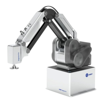
Page 13: Product Introduction
MG400 is an ultra-compact desktop robot arm. It is designed integrating the controller and the robot arm body. The controller is installed in the base. MG400 robot arm includes 4 rotating joints, and two connecting rods (upper arm and forearm), as shown in Figure 3.1. -
Page 14: End Button And Interface
The corresponding diameter of the air pipe is 4mm. Operation terminal MG400 robot supports control through PC and App, as shown in Table 3.2. If you need to use WiFi for control, you need to plug the WiFi module into the controller. -
Page 15: Product Features
Dobot MG400 User Guide Product Features Coordinate system Joint coordinate system The joint coordinate system is determined based on all motion joints. All joints are rotating joints, and the positive rotating direction is shown in Figure 4.1. Figure 4.1 Joint coordinate system... -
Page 16: Tool Coordinate System
Dobot MG400 User Guide Figure 4.2 User coordinate system Tool coordinate system The tool coordinate system defines the tool center point (TCP) and tool posture, of which the origin and orientations vary with the position and angle of the workpiece at the end of robot. The default tool coordinate system is determined based on the end of the robot, as shown in Figure 4.3. -
Page 17: Braking Time And Braking Angle
Dobot MG400 User Guide Figure 4.4 Home point sticker If the home point of the robot arm changes due to the replacement of the transmission parts or the collision, you can calibrate using the calibration block through the control software. See the corresponding software guide for details. -
Page 18: Mechanical Specifications
Dobot MG400 User Guide Mechanical Specifications Dimensions Figure 5.1 MG400 Dimensions Base installation dimensions Issue V1.5 (2023-03-20) User Guide Copyright © Yuejiang Technology Co., Ltd... -
Page 19: End Dimensions
Dobot MG400 User Guide Figure 5.2 Base installation dimensions End dimensions Figure 5.3 End flange dimensions Issue V1.5 (2023-03-20) User Guide Copyright © Yuejiang Technology Co., Ltd... -
Page 20: Workspace
Make sure the tools are properly and safely installed in place. Ensure the safe architecture of tools to prevent accidental fall of any parts. Workspace Figure 5.5 shows the workspace of MG400 robot. NOTICE When operating the robot, be sure to operate within the workspace. Issue V1.5 (2023-03-20) User Guide Copyright ©... -
Page 21: Load Curve
Dobot MG400 User Guide Figure 5.5 Workspace Load curve The load capacity of the robot is negatively correlated with the eccentric distance of the load mass center. The load curve is shown below. Issue V1.5 (2023-03-20) User Guide Copyright © Yuejiang Technology Co., Ltd... - Page 22 Dobot MG400 User Guide Figure 5.6 MG400 load curve Issue V1.5 (2023-03-20) User Guide Copyright © Yuejiang Technology Co., Ltd...
-
Page 23: Electrical Specifications
Dobot MG400 User Guide Electrical Specifications Base Interface Interface overview The base interface board is shown in Figure 6.1 and described in Table 6.1. Figure 6.1 Interface board of the base Table 6.1 Interface description Screen printing Description LAN1 LAN interface The default IP address is 192.168.1.6, which cannot be modified. -
Page 24: Base I/O Interface
For connecting to DC 48V power supply I/O interface Air source interface. The corresponding air pipe diameter was 4mm The ENC interface of the MG400 is shown in Figure 6.2, and described in Table 6.2. Figure 6.2 ENC interface Table 6.2 ENC interface description... - Page 25 Dobot MG400 User Guide below. Figure 6.4 DI connected to simple switch The wiring of DI connected to external DO is shown in Figure 6.5, which takes PNP-type DO without power supply as an example. If DO has its own power supply, you do not need to connect V+ cable.
-
Page 26: Tool I/O Interface
Dobot MG400 User Guide Figure 6.7 DO connected to external load (with external power supply) Tool I/O interface The tool I/O needs to be used with an aerial plug (WEIPU: SF810/P6). Figure 6.8 Tool I/O interface DANGER When connecting end tools, ensure that power interruptions do not cause any hazards, such as a workpiece falling off the tool. -
Page 27: Installation
Dobot MG400 User Guide Installation Installation Environment To maintain the robot performance and ensure safety, please place them in an environment with the following conditions. NOTICE Install indoors with good ventilation. Keep away from excessive and shock. ... -
Page 28: Wiring And Powering On
USB interface and connect wirelessly. Press the power switch. After the robot is turned on, you can debug the robot arm using the control software (DobotStudio Pro or Dobot CRStudio). See the corresponding user guide for details. Figure 7.2 Robot connection NOTICE Issue V1.5 (2023-03-20) - Page 29 Dobot MG400 User Guide Set the specifications and installation method of external cables in compliance with ⚫ local power distribution laws and regulations. Do not remove the controller by yourself, otherwise it may cause electricity leakage. ⚫ Make sure the device is grounded.
-
Page 30: Maintenance And Repair
Remove all parts that do not belong to Dobot. Make a backup copy of the files. Dobot shall not be responsible for the loss of programs, data or files stored in the robot. Restore the robot to the packaging posture. - Page 31 In addition, overall maintenance is required every 20,000 hours of operation time or every 4 years (select the shorter of the two periods for maintenance). If you are not clear about the maintenance processes, please contact Dobot technical engineer. Issue V1.5 (2023-03-20) User Guide Copyright ©...
-
Page 32: Certification
Dobot MG400 User Guide Certification Collaborative robot certification Issue V1.5 (2023-03-20) User Guide Copyright © Yuejiang Technology Co., Ltd... -
Page 33: Robot Reliability Certification
Dobot MG400 User Guide Robot reliability certification Issue V1.5 (2023-03-20) User Guide Copyright © Yuejiang Technology Co., Ltd... -
Page 34: Fcc Sdoc Certification
Dobot MG400 User Guide FCC SDoC certification Issue V1.5 (2023-03-20) User Guide Copyright © Yuejiang Technology Co., Ltd... -
Page 35: Ce-Md Certification
Dobot MG400 User Guide CE-MD certification Issue V1.5 (2023-03-20) User Guide Copyright © Yuejiang Technology Co., Ltd... -
Page 36: Ce-Emc Certification
Dobot MG400 User Guide CE-EMC certification Issue V1.5 (2023-03-20) User Guide Copyright © Yuejiang Technology Co., Ltd... -
Page 37: Rohs
Dobot MG400 User Guide RoHS Issue V1.5 (2023-03-20) User Guide Copyright © Yuejiang Technology Co., Ltd... -
Page 38: Rcm Certification
Dobot MG400 User Guide RCM certification Issue V1.5 (2023-03-20) User Guide Copyright © Yuejiang Technology Co., Ltd... -
Page 39: Kcs Certification
Dobot MG400 User Guide KCs certification Issue V1.5 (2023-03-20) User Guide Copyright © Yuejiang Technology Co., Ltd... -
Page 40: Warranty
12 months (15 months at most if the shipping time is included) after the device is put into use, Dobot shall provide the necessary spare part, and the user (customer) shall offer personnel to replace the spare part, using another part that represents the latest technology level to replace or repairing the related part. -
Page 41: Appendix A Technical Specifications
Dobot MG400 User Guide Appendix A Technical Specifications Product DOBOT MG400 Model DT-MG400-4R075-01 Weight Max load 500g Reach 440mm Power adapter 100V~240V AC, 50/60Hz, Max. 240W Rated voltage DC48V Installation Table installation, indoor Rated power 150W Repeatability ±0.05mm Base size... - Page 42 Dobot MG400 User Guide Working temperature: 0℃~40℃ Operating altitude range ≤ 1000 m Safety Standard EN ISO 10218-1:2011 Steel wire and wire products. General. Test methods EN 60204-1:2018 Safety of machinery. Electrical equipment of machines. General requirements EN ISO 12100:2010 Safety of machinery. General principles for design. Risk...
-
Page 43: Appendix B I/O Simple Circuit
Dobot MG400 User Guide Appendix B I/O Simple Circuit Digital Input The figure below shows the simple digital input circuit and the table below lists the technical specifications. Item Specification Input channel 16 channels Connection method Crimping terminal Input type Input voltage (DC) 24V±10%... - Page 44 Dobot MG400 User Guide Item Specification Connection method Crimping terminal Output type Power supply (DC) 24V±10% Load current of single channel 500mA Output current Isolation method Magnetic isolation Issue V1.5 (2023-03-20) User Guide Copyright © Yuejiang Technology Co., Ltd...
Need help?
Do you have a question about the MG400 and is the answer not in the manual?
Questions and answers