
Related Manuals for Dobot M1


Summary of Contents for Dobot M1
- Page 1 Dobot M1 User Guide Issue: V1.3.4 Date: 2019-05-23 Shenzhen Yuejiang Technology Co., Ltd...
- Page 2 Even if follow this document or any other related instructions, Damages or losses will be happen in the using process, Dobot shall not be considered as a guarantee regarding to all security information contained in this document.
-
Page 3: Preface
Dobot M1 User Guide Preface Purpose This Document describes the functions, technical specifications, installation guide and system commissioning of Dobot M1, making it easy for users to fully understand and use it. Intended Audience This document is intended for: ... -
Page 4: Table Of Contents
Technical Parameters ..................14 Sizes........................15 Hardware Installation ................... 17 Environment Requirements .................... 17 Installing the Base of Dobot M1 ..................17 (Optional) Installing End Effector .................. 18 Installing Laser Engraving Kit ................18 Installing 3D Printing Kit .................. 19 (Optional) Installing Air Pump .................. - Page 5 0 Preface Connecting Network Cable ................46 System Commissioning ....................51 Debugging Dobot M1 ..................51 Debugging the Power of Dobot M1 ..............52 Debugging Emergency Stop Function ............... 53 Debugging Disabling Function ................54 Debugging Motion Function ................55 Debugging Homing Function ................
-
Page 6: Security Precautions
Dobot M1 User Guide 1 Security Precautions Security Precautions This topic describes the security precautions that should be noticed when using this product. Please read this document carefully before using the robot arm for the first time. This product needs... -
Page 7: Service Security
1 Security Precautions People cannot repair and disassemble the robotic arm without professional training. If there is a problem with the robotic arm, please contact Dobot technical support engineer in time. Before operating and maintaining the robotic arm, the personnel responsible for the installation, operation, and maintenance must be trained to understand the various security precautions and to master the correct methods of operation and maintenance. - Page 8 The emergency stop button will be released when rotating to 45 ° Please DO NOT connect the power cable to the Dobot M1 directly without power adapter. Otherwise, the machine will be damaged. Issue V1.3.4 (2019-05-23) User Guide...
-
Page 9: Introduction
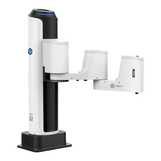
The rated load is 1.5kg, and the repeatability is 0.02mm. Various I/O and communication interfaces are provided for secondary development. Appearance and Constitute Dobot M1 consists of base, Z axis, Rear Arm, Forearm and R axis. Figure 2.1 shows the appearance. Rear arm Forearm... -
Page 10: Working Principle
Figure 2.2 shows the workspace. Figure 2.2 Workspace of Dobot M1 Coordinate System Dobot M1 has two types of the coordinate system, the joint one and the Cartesian one, as shown in Figure 2.3 and Figure 2.4 respectively. NOTE The data shown in Figure 2.3 indicates the mechanical limitation. - Page 11 Dobot M1 User Guide 2 Introduction Figure 2.3 Joint coordinate system Figure 2.4 Cartesian coordinate system Issue V1.3.4 (2019-05-23) User Guide Copyright © Yuejiang Technology Co., Ltd...
-
Page 12: Arm Orientation
Dobot M1 can move to nearly any position and orientation within a given work envelope. You need to specify the arm orientation when Dobot M1 is moving. If you fail to do so, Dobot M1 may move following an unexpected path, resulting in interference with peripheral equipment. -
Page 13: Motion Function
Figure 2.6 Lefty hand orientation Motion Function The motion modes of Dobot M1 include Jogging, Point to Point (PTP), ARC, and CIRCLE. 2.3.4.1 Jogging Mode Jogging mode is to jog Dobot M1 in the Cartesian coordinate system or Joint coordinate system. - Page 14 Dobot M1 User Guide 2 Introduction direction. 2.3.4.2 Point to Point Mode (PTP) PTP mode supports MOVJ, MOVL, and JUMP, which means point to point movement. The trajectory of playback depends on the motion mode. MOVJ: Joint movement. From point A to point B, each joint will run from the initial angle to its target angle, regardless of the trajectory, as shown in Figure 2.7.
- Page 15 Dobot M1 User Guide 2 Introduction In the JUMP mode, if the starting point or the end point is higher than or equal to Limit, or the height that the end effector lifts upwards is higher than or equal to Limit, the trajectory is different to that of Figure 2.8.
- Page 16 Dobot M1 User Guide 2 Introduction Point A is lower than Limit, but point B is higher than Limit. The height of point A and point B are both the same as Limit. Point A and point B are both lower than Limit, but point A plus Height and point B plus Height are higher than Limit.
-
Page 17: Technical Specifications
Dobot M1 User Guide 2 Introduction Figure 2.9 ARC mode 2.3.4.4 CIRCLE Mode (CIRCLE) The CIRCLE mode is similar to the ARC mode and its trajectory is a circle. In the CIRCLE mode, it is necessary to confirm the starting point with other motion modes. -
Page 18: Sizes
Software M1Studio NOTE Mechanical Limitation: Limit the position of Dobot M1 by mechanical parts. Software Limitation: For protection, limit the position of Dobot M1 by software. Sizes Figure 2.10 shows the size of Dobot M1. NOTE Z-axis Motion Range shown in Figure 2.10 indicates the mechanical limitation. - Page 19 Dobot M1 User Guide 2 Introduction Figure 2.10 Size of Dobot M1 Issue V1.3.4 (2019-05-23) User Guide Copyright © Yuejiang Technology Co., Ltd...
-
Page 20: Hardware Installation
3 Hardware Installation Hardware Installation Environment Requirements The operating temperature of Dobot M1 ranges from 5 ° C to 40 ° C. The operating humidity ranges from 45% to 75% (non-condensing). Installing the Base of Dobot M1 The stability of Dobot M1 depends on the installation of the base of Dobot M1. You can design the platform according to the size of the hole of the base and the real environment for fixing Dobot M1. -
Page 21: (Optional) Installing End Effector
3 Hardware Installation (Optional) Installing End Effector You can install the matching gripper, suction cup, or laser on the end of the Dobot M1 for transporting, intelligent sorting and laser engraving. Figure 3.2 shows the size of the end effector of Dobot M1. -
Page 22: Installing 3D Printing Kit
Dobot M1 User Guide 3 Hardware Installation Figure 3.4 connect to Forearm I/O interface Installing 3D Printing Kit shows the 3D printing kit. Figure 3.5 Figure 3.5 3D printing kit Issue V1.3.4 (2019-05-23) User Guide Copyright © Yuejiang Technology Co., Ltd... - Page 23 Dobot M1 User Guide 3 Hardware Installation Procedure Figure 3.6 Connect to Forearm I/O interface Press down the lever on the extruder by hand, and push down the filament to the bottom via a pulley, as shown in Figure 3.7 and Figure 3.8.
-
Page 24: (Optional) Installing Air Pump
Dobot M1 User Guide 3 Hardware Installation Figure 3.8 Push down the filament (2) (Optional) Installing Air Pump It is necessary to install the matching air pump when using the gripper or suction cup for grabbing objects. The air pump is controlled over the I/O interface. For details, please see 6.7 Operating I/O Assistant. - Page 25 Dobot M1 User Guide 3 Hardware Installation NOTE The appearance of the air pump depends on the production batch of Dobot M1. However, the connection method remains unchanged. Table 3.1 Cable Description Color Description VCC_24V Black PGND Yellow OUT1: Control the intake and outtake of the air pump...
- Page 26 Dobot M1 User Guide 3 Hardware Installation Figure 3.11 Standard connection Figure 3.12 Non-standard connection Issue V1.3.4 (2019-05-23) User Guide Copyright © Yuejiang Technology Co., Ltd...
-
Page 27: Electrical Specifications
The addresses of the I/O interfaces of Dobot M1 are unified. Interface Board The interface board of Dobot M1 is located on the back of the base. If the SN number of Dobot M1 is DT211812xxx and later numbers, the interface board is shown in Figure 4.1. -
Page 28: Led Indicators
The LED indicator is steady on when the power adapter is powered on. System indicator All the LED indicators are off when the Dobot M1 is powered off Yellow LED indicator: when powering on the Dobot M1, the yellow LED indicator in the base is steady on for about 15 seconds and then blinks once. -
Page 29: Body I/O Interface
4 Electrical Specifications 4.3.1.1 AC Input Interface NOTICE Figure 4.3 shows the power adapter. For details on how to connect the Dobot M1 to the power adapter, please see 5.2.1 Connecting Power Supply. Figure 4.3 Power adapter Table 4.3 The power adapter input interface description... - Page 30 Dobot M1 User Guide 4 Electrical Specifications The current of the digital output supports 2mA without additional power, whereas the maximum current of the digital output supports 3A with an additional power. 4.3.2.1 Power Interface Table 4.5 Description of the power interface...
- Page 31 Dobot M1 User Guide 4 Electrical Specifications 4.3.2.2 Base I/O Interface Table 4.6 Description of the base I/O interface Name Function Voltage/Current Negative electrode of the logic GND/2A power Positive electrode of the logic 24V DC/2A power RS232_RX RS232 acception...
-
Page 32: External Expansion Interface
Dobot M1 User Guide 4 Electrical Specifications 4.3.2.3 GND Interface Table 4.7 The CAN bus interface description Name Function Voltage/Current PGND Negative of VBUS GND/5A 4.3.2.4 Forearm I/O Interface Table 4.8 The Forearm I/O interface description Name Function Voltage/Current Positive electrode of the logic... - Page 33 Dobot M1 User Guide 4 Electrical Specifications Figure 4.4 DB 62 external expansion board Table 4.9 The external expansion interface description Name Function Voltage/Current EX_IN9(DIN9) Digital input 0V,24V/<100mA PGND Negative of the logic power GND/5A EX_IN10 Reset signal 0V,24V/<100mA (DIN10)...
- Page 34 I/O control will remain in force. At this point, you can use the M1Studio to control the Dobot M1 in the Dobot mode or trigger DIN 15 to make the Dobot M1 run in the offline mode again PGND...
- Page 35 Dobot M1 User Guide 4 Electrical Specifications Name Function Voltage/Current Relay K2 Normally Closed AC: 250V/5A DC:30V/5A Relay K2 Normally Open AC: 250V/5A DC: 30V/5A COM2 Common terminal AC: 250V/5A DC: 30V/5A GND_EMC Earth ground GND/5A FPGA_OUT1 Digital output 0V,24V/2mA (DOUT11)...
- Page 36 Dobot M1 User Guide 4 Electrical Specifications Name Function Voltage/Current IN_A/D3(AIN3) Analog input 0V~10V/<100mA IN_A/D4(AIN4) Analog input 0V~10V/<100mA EX_A1+ Signal input for A phase of external encoder1, reserved EX_A1- Inversion signal input for A phase of external encoder1, reserved EX_B1+...
- Page 37 Dobot M1 User Guide 4 Electrical Specifications Name Function Voltage/Current EX_OUT8 Alarm signal 0V,24V/2mA (DOUT8) VCC_24V Positive of the logic power 24V/3A VCC_24V Positive of the logic power 24V/3A PGND Negative of the logic power GND/5A CAN2_H CAN bus, reserved...
- Page 38 COM, NC, NO interfaces directly on the external expansion board after connecting it to the Dobot M1. If you have to debug the relay K1 and K2, you can debug OUT09 and OUT10 on the M1Studio > I/O Assistant page.
-
Page 39: Communication Interface
Figure 4.5 Circuit diagram Communication Interface 4.3.4.1 Ethernet Interface Dobot M1 can connect to a PC over the standard RJ45 Socket interface, using TCP/IP protocol. 4.3.4.2 RS-232 Interface Dobot M1 can connect to a PC over standard the RS-232 interface. -
Page 40: Installation And Commissioning
Dobot M1 User Guide 5 Installation and Commissioning Installation and Commissioning Installing Software The main software for Dobot M1 is M1Studio. You can use playback, script control, 3D printing, etc. Environment Requirements The supported OSs are as follows. Win7 ... - Page 41 Dobot M1 User Guide 5 Installation and Commissioning Figure 5.1 The M1Studio installation GUI After 40 seconds later, the FTDI CDM Drivers page is displayed, as shown in Figure 5.2. Figure 5.2 FTDI CDM Drivers GUI Issue V1.3.4 (2019-05-23) User Guide...
-
Page 42: Verifying Installation
Dobot M1 User Guide 5 Installation and Commissioning Verifying Installation Please double-click the M1Studio after installation. If the M1Studio can be started, the installation is successful. Troubleshooting If the M1Studio is not running, you need to install all VC++ libraries in the C:\Program Files\M1Studio\attachment directory, as shown in Figure 5.3. - Page 43 Dobot M1 User Guide 5 Installation and Commissioning Figure 5.4 Power cables and power adapter The input and output interfaces of the power adapter are shown in Table 5.1 Table 5.2 Table 5.1 The power adapter input interface description Name...
- Page 44 Dobot M1 User Guide 5 Installation and Commissioning Procedure Figure 5.5 Connect power supply input cable to power adapter NOTICE If the type of the AC power cable is America-standard, please connect the G pin on the AC power cable to the Ground pin on the power adapter, the W pin to the N pin, and the Z pin to the L pin.
- Page 45 Dobot M1 User Guide 5 Installation and Commissioning Figure 5.6 Connect power supply output cable to power adapter Issue V1.3.4 (2019-05-23) User Guide Copyright © Yuejiang Technology Co., Ltd...
-
Page 46: Connecting Emergency Stop Switch
Figure 5.7 Connect to Dobot M1 Connecting Emergency Stop Switch Before operating the Dobot M1, please connect it to the emergency stop switch to ensure that the Dobot M1 can be stopped immediately during running. When powering on the Dobot M1 for the first time, please ensure that the emergency stop switch has been opened (The emergency stop button is released ). -
Page 47: Connecting Serial Port
DB9 adapter cable by yourself. Please check the SN number on the M1Studio > Help > About M1Studio page. NOTICE If you have connected a Dobot M1 to a PC with the USB to DB9 adapter cable, you cannot connect them with a network cable. Choose one of the connection methods. Procedure Issue V1.3.4 (2019-05-23) - Page 48 Dobot M1 User Guide 5 Installation and Commissioning Figure 5.10 Serial port connection (1) Figure 5.11 Serial port connection (2) Issue V1.3.4 (2019-05-23) User Guide Copyright © Yuejiang Technology Co., Ltd...
-
Page 49: Connecting Network Cable
Figure 5.12 Serial information of M1Studio Connecting Network Cable In addition to the USB to serial line, you can also use a network cable to connect Dobot M1 and PC, but both connection ways cannot be supported at the same time, to avoid connection failure. - Page 50 5 Installation and Commissioning Figure 5.13 Direct connection If the SN number of Dobot M1 is DT211812xxx and later numbers, please connect them as the flowing steps. Please check the SN number on the M1Studio > Help > About M1Studio page.
- Page 51 Connect, as shown in Figure 5.15. Figure 5.15 IP address information If the SN number of Dobot M1 is DT211811xxx and earlier numbers, please connect them as the flowing steps. If the local IP address, subnet mask of the PC are 192.168.1.10, 255.255.255.0 respectively.
- Page 52 If Network Status of Dobot M1 turns to Connected to LAN, the modification is successful. 5.2.4.2 Connecting Via Router This topic describes how to connect the PC to the Dobot M1 with a router and a PC can control multiple Dobot M1 simultaneously. NOTICE Forced configuration function is recommended only when a PC controls a Dobot M1.
- Page 53 If the IP address is not displayed on the upper left pane of the M1Studio page after powering on the Dobot M1, please obtain the IP address as the following steps. If Connect turns to Disconnect, the connection is successful.
-
Page 54: System Commissioning
5 Installation and Commissioning System Commissioning The origin and other settings of Dobot M1 have been set by default, Dobot M1 can be directly put in use. After Dobot M1 is installed and the cables connected are checked, the system commissioning can be performed. -
Page 55: Debugging The Power Of Dobot M1
You have connected the Dobot M1 to an emergency stop switch. Procedure Hold down the power button in the base of Dobot M1 for about 5 seconds, and then release the button. If all LED indicators are off and the Dobot M1 moves down automatically, the Dobot M1 is powered off successfully. -
Page 56: Debugging Emergency Stop Function
The Dobot M1 has been connected to an emergency stop switch. Procedure Figure 5.20 Emergency stop Dobot M1 is stopped immediately with an alarm about emergency stop and the red LED indicator on the base is on, which indicates that the emergency stop function is normal. -
Page 57: Debugging Disabling Function
Dobot M1 User Guide 5 Installation and Commissioning Figure 5.22 Alarm tab Debugging Disabling Function You can disable the motor of Dobot M1 to make it in the open-loop state, and then move the Dobot M1 by hand. Prerequisites ... -
Page 58: Debugging Motion Function
Dobot M1 is in the open-loop state. If Dobot M1 can be moved by hand, the disabling function is OK. Debugging Motion Function For details about motion functions supported by Dobot M1, please see 2.3.4 Motion Function. 5.3.5.1 Debugging Jogging Function Prerequisites ... - Page 59 The procedure for debugging Joint coordinates is similar to that for debugging Cartesian coordinates. You need to select Joint on the Operation Panel page, and then Click J1+, J1-, J2+, J2-, J3+, J3-, J4+, and J4- to jog Dobot M1. Figure 5.24 Cartesian coordinate mode The jogging velocity is the maximum velocity multiplying the corresponding percentage.
-
Page 60: Debugging Homing Function
Dobot M1 User Guide 5 Installation and Commissioning You can click Y+, Y-, Z+, Z-, R+, and R-, to make the Dobot M1 jog along the Y, Z, or R axis in the negative or positive direction. 5.3.5.2 Debugging Playback Function Prerequisites ... - Page 61 5 Installation and Commissioning After parts (motors, reduction gear units, battery, etc.) have been replaced or the robotic arm has hit the workpiece, the origin of the Dobot M1 will be changed. You need to operate the homing procedure after resetting the origin.
- Page 62 Dobot M1 User Guide 5 Installation and Commissioning After the homing procedure is completed, the coordinate of the homing point is shown in Figure 5.25. If the coordinate you get is quite different from Figure 5.25, it indicates that the homing procedure is failed, please re-execute again.
-
Page 63: Operation
Alarms Description If teaching or saving point is incorrect, for example, the Dobot M1 moves to where a point is at a limited position or a singular position, the Dobot M1 will generate an alarm. For details, please see Table 6.2. When an alarm is generated, the red LED indicator on the base will be on. - Page 64 In the MOVJ or JUMP mode, if the two points are the same, only different in arm orientations, J1 or J4 may be limited when moving the Dobot M1, resulting in an alarm generated. You need to modify and resave these points and then clear the alarm manually.
- Page 65 Dobot M1 User Guide 6 Operation The Dobot M1 has been connected to the PC successfully. The Dobot M1 has been connected to the emergency stop switch. Procedure The Alarm Log is displayed. Figure 6.1 Alarm tips Figure 6.2 Alarm GUI shows the description of the alarm button.
-
Page 66: Saving Point In Arc Mode
The Dobot M1 has been connected to the PC successfully. The Dobot M1 has been connected to the emergency stop switch. Procedure NOTICE You need to use other motion modes to confirm the starting point of the arc trajectory because the middle point and the end point only can be confirmed in ARC mode. - Page 67 A is the starting point, point C is the end point, as shown in Figure 6.3. Figure 6.3 Arc trajectory NOTICE You cannot set the pause time when point A moves to point B. Otherwise, Dobot M1 will not work. Issue V1.3.4 (2019-05-23) User Guide Copyright ©...
-
Page 68: Saving Point In Jump Mode
3.4 (Optional) Installing Air Pump. Application Scenario If you want to use the Dobot M1 to transport, intelligent sort, write and draw, the teaching and playback function of Dobot M1 can help you to complete. This section uses the suction cup as the end effector to describe how to operate. - Page 69 If you save a point after an alarm is generated, the saved point is unavailable. You need to jog the Dobot M1 to clear the alarm, and then save the point again. However, if an alarm about singular point is generated when implementing jogging, the saved point is available in JUMP and MOVJ mode.
- Page 70 Dobot M1 User Guide 6 Operation The saved point information of which Type is JUMP is displayed on the left pane of the Playback page, as shown in Figure 6.6. Figure 6.6 The coordinate display Figure 6.7 Motion command setting Issue V1.3.4 (2019-05-23)
- Page 71 6 Operation NOTICE In the JUMP mode, if lifting Dobot M1 to the maximum height is not necessary after lifting to a certain height, please unselect Use Limit. The saved point information of which Type is Wait is displayed on the left pane of the Playback page.
-
Page 72: Other Function Description
Set the loop number of the saved point when implementing playback. The maximum value is 9999. You can also select Infinite Loop to make the Dobot M1 in the infinite loop state when implementing playback according to the saved points list, as shown in Figure 6.8. - Page 73 Dobot M1 User Guide 6 Operation Figure 6.9 Overwrite the current saved point Table 6.4 lists the location description of a saved point. Table 6.4 Description of the location of a saved point Insert Location Description Add At Last Add a new point after the last saved point.
- Page 74 Dobot M1 User Guide 6 Operation Table 6.5 Parameter Description of the saved point Parameter Description Type The command type of Dobot M1 Value: JUMP MOVJ MOVL The method to save points in the CIRCLE mode is the CIRCLE: same as that of ARC mode.
- Page 75 Dobot M1 User Guide 6 Operation Figure 6.11 Right-click options of the saved points list When modify the coordinates displayed in Content of which Type is motion mode, you can input the coordinate values manually or operate the operation panel to modify them.
-
Page 76: Scripting
The Dobot M1 has been connected to an emergency stop switch. Application Scenario You can control a Dobot M1 over scripting. Dobot M1 supports various API, such as velocity/acceleration setting, motion mode setting, and I/O configuration, which uses Python language for secondary development. For details about the Dobot M1 API interface and function description, please see Dobot API Interface Document. -
Page 77: Operating Blockly
NOTICE If you use the motion command when writing a program, please add the orientation command before every motion command, which indicates the arm orientation of Dobot Figure 6.14 Write a script The Save Scrip File page is displayed. - Page 78 The Dobot M1 has been connected to a PC successfully. The Dobot M1 has been connected to an emergency stop switch. Application Scenario Blockly is a programming platform based on Google Blockly. You can program through the puzzle format, which is straightforward and easy to understand.
-
Page 79: Operating Laser Engraving
Operating Laser Engraving Prerequisites The Dobot M1 has been powered on. The Dobot M1 has been connected to a PC successfully. The laser kit has been installed. For details, please see 3.3.1 Installing Laser Engraving Kit. ... - Page 80 Dobot M1 User Guide 6 Operation Figure 6.16 Laser Engraving GUI The picture (such as BMP, JPEG, JPG, PNG, and so on) is supported. Figure 6.17 Import picture NOTICE Issue V1.3.4 (2019-05-23) User Guide Copyright © Yuejiang Technology Co., Ltd...
- Page 81 Motor on the Operation Panel pane of the M1Studio page and move the Dobot M1 by hand to a proper height, to make the laser dot appeared on the material burn the brightest. When the laser power is enough, you can view burning marks on the material.
-
Page 82: Operating 3D Printing
The Dobot M1 has been powered on. You have connected the Dobot M1 to a PC over a network cable, and the IP address of Dobot M1 and the PC must be in the same network segment. For details, please see 5.2.4 Connecting Network Cable. - Page 83 The printing platform has been prepared and please place it in the workspace. NOTICE If the SN number of Dobot M1 is DT2118xxxxx and later numbers, please switch 3D printing mode directly to start 3D printing without an update. If you need to update the 3D printing firmware, please see 6.9.2 Upgrading Firmware.
- Page 84 6 Operation Figure 6.20 Complete 3D printing switching Unplug the network cable between the Dobot M1 and PC, and connect the Dobot M1 to the PC with the USB to DB9 adapter cable. Select Machine > settings on the Cura page.
- Page 85 Baud rate Please set to 115200 NOTE The maximum width of 3D printing that Dobot M1 supports is 200mm, the maximum depth is 200mm, and the maximum height is 220mm. Please make the 3D-print in the Dobot M1 workspace. Set slice parameters, and select File > Open Profile to import these parameters, as shown in Figure 6.22.
- Page 86 M1Studio. Please replace it based on site requirements. Figure 6.23 Configuration sample Dobot-2.0-Vase.ini is used for printing a thin-walled vase, while Dobot-2.0-ini is used for the filling, the filling rate is 20%. Click , the Open 3D model page is displayed, and select the 3D printing model prepared.
- Page 87 Set Temperature to 200 and press down Enter to heat the extruder. The temperature of the extruder should be above 170℃. The Dobot M1 will not start 3D printing until the filament is in the melting state. So you need to heat the extruder first.
- Page 88 If the melted filament flows from the nozzle of the extruder, the extruder is working properly. Click -Z or Click 10, 1, 0.1 to move the Dobot M1 to the position where the distance from the nozzle to the printing platform is about 0.3mm, as shown in Figure 6.27.
-
Page 89: Operating I/O Assistant
Figure 6.28 Input command M415 NOTICE If the yellow LED indicator is always on when printing a 3D module, the connection between the Dobot M1 and 3D printing kit is poor. Please check the connection and restart the Dobot M1. Operating I/O Assistant Prerequisites ... -
Page 90: Operating Collision Detection
The Dobot M1 has been connected to a PC successfully. The Dobot M1 has been connected to an emergency stop switch. Procedure Remove the fixture on the robot arm and make sure that there are no obstacles within the workspace. - Page 91 During robot arm running, please do not perform any other operation on the Dobot M1 or power off it, to avoid the Dobot M1 in an abnormal condition When the unexpected occurs during robot arm running, please click Stop on the Dynamic Setting page.
- Page 92 Dobot M1 User Guide 6 Operation Figure 6.31 Obtain kinetic parameters Click Save and Quit. The kinetic parameters are saved in the main controller. The Safe Mode Setting page is displayed. At this point, the parameters in the Set Params section will be generated automatically as the set sensitivity level, as shown in Figure 6.32.
- Page 93 Activate collision detection and the speed decreases Figure 6.33 Set payload Table 6.10 Post-collision measure description Parameter Description EX Force Restart Dobot M1 continues the current task by the external force (Horizontal) 5s Restart Dobot M1 continues the current task automatically Issue V1.3.4 (2019-05-23) User Guide...
-
Page 94: Operating Web Management
Operating Web Management The web management of Dobot M1 integrates offline file management, firmware update, and application update, which is used to upload the offline files, make the Dobot M1 in the offline mode, and update the applications. Managing Offline File You can upload the scripts, the blockly programs, or the saved points lists that have been saved on a local PC to Dobot M1 using the web management, to perform offline operation. - Page 95 Dobot M1 User Guide 6 Operation The Offline Script Management page is displayed. The Add File page is displayed. The uploaded file dialog box is displayed, as shown in Figure 6.34. Figure 6.34 Upload files Only support the files, of which the suffixes are .playback, .blockly, and .script.
-
Page 96: Upgrading Firmware
DANGER When updating a firmware, please do not perform any other operation on the Dobot M1 or power off it, to avoid Dobot M1 in an abnormal condition. Otherwise, it will be vulnerable to injury the device or the person. - Page 97 6 Operation Prerequisites You have connected the Dobot M1 to a PC over network cable, and the IP addresses of Dobot M1 and the PC must be in the same network segment. For details, please see 5.2.4 Connecting Network Cable.
- Page 98 Dobot M1 User Guide 6 Operation is successful. Figure 6.39 Update A9 firmware The Update Firmware page is displayed, as shown in Figure 6.40. Figure 6.40 Update Firmware GUI Issue V1.3.4 (2019-05-23) User Guide Copyright © Yuejiang Technology Co., Ltd...
- Page 99 You can view the process of the firmware upgrade. If the progress bar is 100% and the green LED indicator on the base of Dobot M1 is blinking, the update is completed, as shown in Figure 6.42 and Figure 6.43. And then the next firmware update can be started.
-
Page 100: Example
When updating a firmware, please do not perform any other operation on Dobot M1 or power off it, to avoid Dobot M1 in an abnormal condition. Otherwise, it will be vulnerable to injury the device or the person. After the 3D printing firmware is updated, Dobot M1 will switch to 3D printing mode, you need to switch the Dobot M1 to Dobot mode. - Page 101 Dobot M1 User Guide 6 Operation Figure 6.45 Trajectory of Dobot M1 Figure 6.46 Cartesian coordinate of the trajectory If point A is the starting point, and Point B is the end point. From Point A to Point J, the coordinates are listed as Table 6.11.
- Page 102 Dobot M1 User Guide 6 Operation Point Coordinate (x,y,z,r) (366,111,110,0) (194,111,110,0) (194,277,110,0) (85,250,110,0) (-44.4458,239.5284,110,33.08) (The middle point of the arc) (-120.6913,164.5902,110,65.6601) (372.225,-63.2786,110, -148.8402) (351.7533,-113.7360,110, -160.2802) (The middle point of the circle) (323.1731,-115.7006,110, -170.5002) Figure 6.47 shows an example of the saved points list.
-
Page 103: Example Of The External Drive
Figure 6.48 shows the connection between the I/O interface and control device without additional power. VCC_24V is the output voltage of the I/O interface of Dobot M1. OUTx is the output of the I/O interface (assuming that OUT0 and OUT1). Please select the proper outputs based on site requirements. -
Page 104: Example Of Switching The Arm Orientation At The Same Point
In MOVJ or JUMP mode, if the two points are the same, only different in arm orientations, J1 or J4 may be limited when the Dobot M1 is moving, resulting in an alarm generated. You need to modify and resave the point for which the alarm is generated, and then clear the alarm manually. - Page 105 The Dobot M1 has been connected to a PC successfully. For details, please see 5.2.3 Connecting Serial Port or 5.2.4Connecting Network Cable. If the server is the main controller, you must connect the Dobot M1 to a PC with a network cable.
- Page 106 Dobot M1 User Guide 6 Operation import socketserver import time import math class ThreadedTCPRequestHandler(socketserver.BaseRequestHandler): def setup(self): ip = self.client_address[0].strip() port = self.client_address[1] print(ip+":"+str(port)+" is connect!") def handle(self): while True: # add while for keep link data = self.request.recv(1024) if data:...
- Page 107 (strCMD == "MoveP1" or strCMD == "p1"): // Send Move P1 or P1 command, Dobot M1 will move as the following commands dType.SetArmOrientation(api, 1, 1) dType.SetPTPCmd(api, 0, 229, 212, 120, 0, 1) dType.SetARCCmd(api, [62,265,120,50], [-58,266,120,76], 1) elif (strCMD == "MoveP2"...
- Page 108 Dobot M1 User Guide 6 Operation server.serve_forever() NOTE The way to import the script depends on the server, please select based on site requirements. If the server is the PC where the M1Studio is located, please execute the following steps.
- Page 109 6 Operation Select Offline Mode from the drop-down list on the Mode Switch Controlling pane of the Home page, and click Start to make Dobot M1 in the Offline Mode status, as shown in Figure 6.53. Now, the blue LED indicator on the base of Dobot M1 is blinking.
-
Page 110: Example Of External Expansion I/O Control
Dobot M1 User Guide 6 Operation Figure 6.54 Configure client Now, the Dobot M1 will move as the motion commands in the script. Figure 6.55 Send commands on the client Example of External Expansion I/O Control Issue V1.3.4 (2019-05-23) User Guide... - Page 111 You have launched M1Studio. You have connected Dobot M1 to a PC over network cable or router, and the IP addresses of Dobot M1 and the PC must be in the same network segment. For details, please see 5.2.4Connecting Network Cable.
- Page 112 Dobot M1 User Guide 6 Operation Figure 6.57 Connection Demo Procedure Figure 6.58 Connect to external expansion I/O interface Issue V1.3.4 (2019-05-23) User Guide Copyright © Yuejiang Technology Co., Ltd...
- Page 113 DIN13 Pause signal DIN14 Stop signal After this signal is triggered, the Dobot M1 will stop offline running while the external I/O control will remain in force. At this point, you can use the M1Studio to control the Dobot M1...
- Page 114 Dobot M1 User Guide 6 Operation NOTE All signals Table 6.13 are falling edge triggered. Select the corresponding IP address from the serial drop-down list on the upper left pane of the M1Studio page and click Connect. Click Tools > Web Management > Upload Offline Script to upload the script to the main controller, as shown in Figure 6.60.
-
Page 115: Example Of Relay Connection
Trigger Y5 and the Dobot M1 will run in the offline mode. If stopping the Dobot M1 running in the offline mode is required, please trigger Y4. At this point, the Dobot M1 stops offline running, while the external I/O control remains in force. If continuing the Dobot M1 running in the offline mode is required, please trigger Y5 directly. - Page 116 The Dobot M1 has been connected to an emergency stop switch. The Dobot M1 has been connected to a DB62 external expansion board. Procedure Take the relay K2 as an example. Set the multimeter to Continuity mode and connect one probe to COM2 interface, and connect the other probe to NC2 interface.
- Page 117 Dobot M1 User Guide 6 Operation Figure 6.64 Connect to magnetic valve Issue V1.3.4 (2019-05-23) User Guide Copyright © Yuejiang Technology Co., Ltd...
-
Page 118: Maintenance
Dobot M1 User Guide 7 Maintenance Maintenance Routine Maintenance Routine Inspection Due to the temperature, humidity, dust, and vibration, the components will be aged, leading to reducing product service life. Performing maintenance inspections and procedures properly is essential for preventing trouble and ensuring safety. Especially in high-temperature environment, frequently start-stop scenario, and other special scenarios, you need to shorten the inspection period. -
Page 119: Periodic Inspection
Dobot M1 User Guide 7 Maintenance Item Operating state Inspection point Solution indicators indicators are displayed replace the corresponding buttons normally components timely emergency stop switch is working regularly Periodic Inspection In order to keep the good operation of the robotic arm, please check the place where it is hard to check regularly. -
Page 120: Cleaning Maintenance
Dobot M1 User Guide 7 Maintenance Item Operating state Inspection point Inspection period Solution Bolt, screw Check 12 months that happens, whether please tighten them screws bolts around each joint of robotic arm are loose Check whether screws... -
Page 121: Maintenance Of Mechanical Parts
If there is no grease on the air-laid paper, the grease is used up. Procedure If Connect turns to Disconnect, the connection is successful, and the Dobot M1 can be controlled by the M1Studio. Figure 7.1 Screw rod of Z-axis Issue V1.3.4 (2019-05-23) -
Page 122: Greasing Guide Rail Of Z-Axis
Please prepare the correct-size syringe (a diameter of no more than 2cm) and needle to ensure that the syringe can touch the guide rail of Z-axis. Procedure After 15 minutes, restart the Dobot M1 to put it into use. Figure 7.2 Guide rail of Z-axis Issue V1.3.4 (2019-05-23) User Guide Copyright ©... -
Page 123: Maintenance Of Electrical Parts
NOTICE Only the Dobot M1 of which the SN number is DT2118xxxxx and later numbers has installed the homing switch. If not, this procedure is not supported. xxx indicates the random number, please replace it based on site requirements. - Page 124 Dobot M1 User Guide 7 Maintenance Figure 7.3 Low battery voltage operation guide (1) Figure 7.4 Low battery voltage operation guide (2) Issue V1.3.4 (2019-05-23) User Guide Copyright © Yuejiang Technology Co., Ltd...
- Page 125 J1 and J2 move to the limit as lefty hand orientation with signals triggered by homing switches of J1 and J2, and move backward at low speed to separate from the homing switches, and then stop moving, indicating that the Dobot M1 has moved to the homing point.
- Page 126 7 Maintenance 7.3.1.2 Replacing Encoder Battery The battery is located on the main controller of the base or on the Forearm. The position of the battery depends on the production batch of Dobot M1. Warning If a fuse is not installed on the battery, please contact the technical support engineer.
- Page 127 If the SN number of Dobot M1 is earlier than DT2118xxxxx, the Encoder battery is located on the base of the Dobot M1. If the SN number of Dobsot M1 is DT2118xxxxx and later numbers, the Encoder battery is located on the Forearm of the Dobot M1.
- Page 128 Dobot M1 User Guide 7 Maintenance battery to be replaced on the Forearm instead of the base. For details, please see Step 4 to Step 9. If a fuse is installed on the battery, please cut off the zip-tie that fixed the original battery, as shown in Figure 7.8.
- Page 129 Dobot M1 User Guide 7 Maintenance Figure 7.9 Disconnect the connector of the battery from the battery adaptor cable If a fuse is not installed on the battery, please remove the cover of the battery holder to take out the original battery and unplug the battery connector of bus cable connecting to the battery holder, as shown in Figure 7.10.
- Page 130 Remove the Forearm cover with 2.5mm hexagon wrench and cross head screw- driver, as shown in Figure 7.11. Figure 7.11 Forearm of Dobot M1 Cut off the zip-tie that fixed the original battery, as shown in Figure 7.12. Figure 7.12 Location of battery holder on Forearm Remove the original battery and disconnect the connector of the battery from Issue V1.3.4 (2019-05-23)
- Page 131 Dobot M1 User Guide 7 Maintenance the battery adapter cable, as shown in Figure 7.13. Figure 7.13 Disconnect the battery from the battery adapter Issue V1.3.4 (2019-05-23) User Guide Copyright © Yuejiang Technology Co., Ltd...
- Page 132 Dobot M1 User Guide 7 Maintenance Figure 7.14 Connect the battery adapter to the battery interface NOTE There are two battery interfaces on the Driver Board, as shown in the red box of Figure 7.15. You need to connect the battery adapter to the unused battery interface.
- Page 133 Dobot M1 User Guide 7 Maintenance Figure 7.16 Connect the battery to the battery adapter Figure 7.17 Insert wire tie Figure 7.18 Put battery into the battery holder Issue V1.3.4 (2019-05-23) User Guide Copyright © Yuejiang Technology Co., Ltd...
- Page 134 Select the corresponding serial port from the serial drop-down list, and click Connect. If Connect turns to Disconnect, the connection is successful, and the Dobot M1 can be controlled by the M1Studio. Click Reset Encoder1, Reset Encoder2, Reset Encoder3, and Reset Encoder4 respectively on the Debug page to reset J1 Encoder, J2 Encoder, J3 Encoder and J4 Encoder, as shown in Figure 7.19.
- Page 135 Dobot M1 in the open-loop state. Jog the Dobot M1 by hand to make the Rear Arm and Forearm in a straight line and perpendicular to the base forward, and then jog the Dobot M1 to the bottom of Z-axis, as shown in Figure 7.20.
-
Page 136: Calibration
The Dobot M1 has been connected to the emergency stop switch. The pen holder kit has been installed on the end of the Dobot M1. The size of the pen holder should be match with the size of the end of the Dobot M1. For details, please see 3.3 (Optional) Installing End Effector. - Page 137 If Connect turns to Disconnect, the connection is successful, and the Dobot M1 can be controlled by M1Studio. Move the Dobot M1 with righty hand orientation to touch the calibrated point that is on the A4 sheet of paper, as shown in Figure 7.22.
- Page 138 Dobot M1 User Guide 7 Maintenance Figure 7.22 Calibration as righty hand orientation The value of P1 is J2 coordinate with righty hand orientation, as shown in Figure 7.23. Issue V1.3.4 (2019-05-23) User Guide Copyright © Yuejiang Technology Co., Ltd...
- Page 139 Dobot M1 User Guide 7 Maintenance Figure 7.23 Save J2 coordinate with righty hand orientation Figure 7.24 Calibration with righty hand orientation The value of P2 is J2 coordinate with lefty hand orientation, as shown in Figure 7.25. Issue V1.3.4 (2019-05-23) User Guide Copyright ©...
- Page 140 7 Maintenance Figure 7.25 Calibration as lefty hand orientation NOTICE After saving P1 and P2, you cannot click Confirm until the motor of Dobot M1 is in the closed-loop state. DANGER The Dobot M1 starts to work after clicking Confirm. Please do not enter the workspace of the robotic arm, otherwise, it will be vulnerable to injury the device or the person.
Need help?
Do you have a question about the M1 and is the answer not in the manual?
Questions and answers