
Related Manuals for Dobot CR16


Summary of Contents for Dobot CR16
- Page 1 User Guide Dobot CR16 Hardware User Guide Issue: V1.3 (Translated Version) Date: 2021-07-07 Shenzhen Yuejiang Technology Co., Ltd...
- Page 2 Even if follow this document or any other related instructions, Damages or losses will be happening in the using process, Dobot shall not be considered as a guarantee regarding all security information contained in this document.
- Page 3 Dobot CR16 Hardware User Guide Preface Purpose This Document describes the functions, technical specifications, installation guide of DOBOT CR16 robot, making it easy for users to fully understand and use it. Intended Audience This document is intended for: Customer ...
-
Page 4: Table Of Contents
Dobot CR16 Hardware User Guide Contents Security Precautions ....................1 Security Warning Sign ...................... 1 General Security........................ 1 Personal Security ......................5 Overview ........................7 Technical Specifications ....................7 Robot Body Technical Parameters ............... 7 Controller Technical Parameters ................9 Product Size ........................ - Page 5 Dobot CR16 Hardware User Guide Controller Installation Location................. 39 Robot Installation Location ................40 Connecting cables ......................41 Precautions ......................41 Connecting Controller and Robot by Heavy Duty Cables ......... 41 Connecting Emergency Stop Switch ..............42 Connecting WiFi Module .................. 43 Connecting to Power Supply ................
-
Page 6: Security Precautions
Dobot CR16 Hardware User Guide Security Precautions This topic describes the security precautions that should be noticed when using this product. Please read this document carefully before using the robot for the first time. This product needs to be carried out in an environment meeting design specification. You cannot remold the product without authorization, otherwise, it could lead to product failure, and even personal injury, electric shock, fire, etc. - Page 7 Dobot CR16 Hardware User Guide circuit, otherwise, it is vulnerable to injury the device or the person. You should comply with the local laws and regulations when operating the robot. The security precautions in this document are only supplemental to the local laws and regulations.
- Page 8 Dobot CR16 Hardware User Guide Shenzhen Yuejiang Technology Co., Ltd. assumes no responsibility for robot damage or personal injury caused by failure to follow product instructions or other improper operations. Handling operations such as lifting rings and driving need to use appropriate and reliable lifting equipment.
- Page 9 Dobot CR16 Hardware User Guide correct. If the controller needs to be restarted due to power failure, when restarting, the robot must be manually returned to the initial position of the automatic operation program before restarting the automatic operation.
-
Page 10: Personal Security
Dobot CR16 Hardware User Guide Be careful during the robot carrying or installing. Please follow the instructions on the packing box to put down the robot gently and place it correctly in direction of the arrow. Please use the matched cables when connecting a robot to internal or external equipment for personal security and equipment protection. - Page 11 Dobot CR16 Hardware User Guide Please ensure that the robot establishes safety measures near the operation area, such as guardrails, to protect the operator and surrounding people. Issue V1.3 (2021-07-07) User Guide Copyright © Yuejiang Technology Co., Ltd...
-
Page 12: Overview
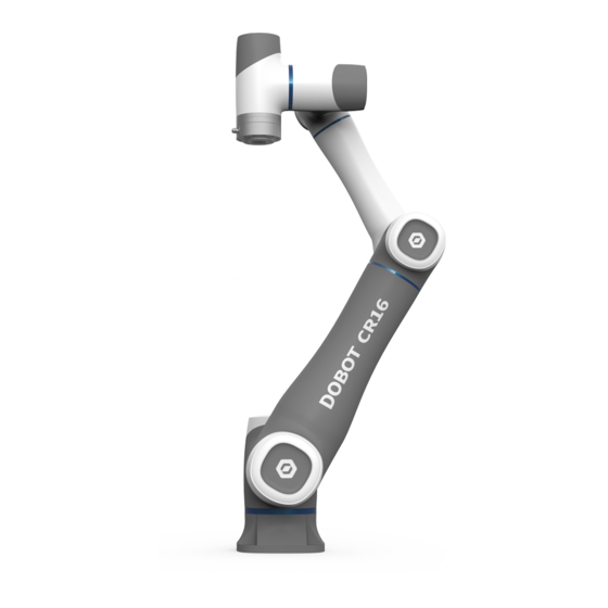
DOBOT CR16 has a repeat positioning accuracy of ± 0.03mm, a max load of 16k kg. It is a product with the advantages of both industrial robots and collaborative robots. - Page 13 Dobot CR16 Hardware User Guide Rated Voltage DC 48V Maximum Power 400 W Maximum Speed of 3 m/s End-effector ±360° ±360° ±160° Motion Range (° ) ±360° ±360° ±360° 120° /s 120° /s 180° /s Joint Maximum Speed(° /s) 180° /s 180°...
-
Page 14: Controller Technical Parameters
Dobot CR16 Hardware User Guide CSA Z434-14 (R2019) Industrial robots and robot systems NFPA 79:2018 Electrical Standard for Industrial Machinery EN ISO 10218-1:2011 Steel wire and wire products. General. Test methods EN 60204-1:2018 Safety of machinery. Electrical equipment of machines. -
Page 15: Product Size
Dobot CR16 Hardware User Guide Programming Script/ Graphical Programming Language Installation Method Floor mounting Temperature: 0℃ - 45℃ Environment Humidity: ≤95%, and no condensation Protection Grade IP20 Cooling Method Forced air cooling Safety Function Emergency stop function and reserved external safety interface (can be controlled by... -
Page 16: Controller Size
Dobot CR16 Hardware User Guide Figure 2.2 Robot body size Controller Size Figure 2.3 Controller size Nameplate Description The nameplate includes the product name, model number, weight and certification mark, as shown in Figure 2.4. Issue V1.3 (2021-07-07) User Guide... -
Page 17: Security Warning Labels
The specific content of the warning labels is shown in Figure 2.5. Figure 2.5 Security warning labels Robot Workspace Figure 2.6 shows the workspace of CR16 robot. Issue V1.3 (2021-07-07) User Guide Copyright © Yuejiang Technology Co., Ltd... -
Page 18: End-Effector Size
Dobot CR16 Hardware User Guide Figure 2.6 CR16 robot workspace End-effector Size Issue V1.3 (2021-07-07) User Guide Copyright © Yuejiang Technology Co., Ltd... -
Page 19: End-Effector Load Description
Dobot CR16 Hardware User Guide Figure 2.7 End-effector Size End-effector Load Description The robot actuator can bear the load of the cylinder whose center of mass is located at an axial distance of LD80mm from the center of the End -effector and a radial distance of LR60mm and no more than 16kg. -
Page 20: Home Description
Dobot CR16 Hardware User Guide Table 2.3 Stop time and angle Stop angle(° ) Axis Stop time(ms) 10.18 14.09 15.24 4.76 4.48 4.74 Home Description After some parts (motors, reduction gear units) of the robot have been replaced or the robot has been hit, the origin of the robot will be changed. -
Page 21: Product Features
Dobot CR16 Hardware User Guide Figure 2.10 Factory posture Product Features Motion Function The motion trajectory consists of a series of interpolated motions since the interpolated motion is the basic motion type. According to the different trajectories, motion functions are classified as joint interpolated motion, linearly interpolated motion, circular interpolated motion and continuous path. - Page 22 Dobot CR16 Hardware User Guide Figure 2.12 Move mode Jump: The trajectory looks like a door. From point A to point B, the robot will move in the Move mode Move up to the lifting height (StartHeight is a relative height).
- Page 23 Dobot CR16 Hardware User Guide Figure 2.14 Jump mode (1) If the heights of point A and point B are the same with zLimit, the trajectory is shown in Figure 2.15. Figure 2.15 Jump mode (2) 2.11.1.3 ARC (Circular Interpolated Motion) The trajectory is an arc, which is determined by three points (the current point, any point and the end point on the arc), as shown in Figure 2.16.
-
Page 24: Coordinate System
2.11.2.1 Joint Coordinate System The Joint coordinate system is determined by the motion joints. Figure 2.18 shows the Joint coordinate system of a CR16robot. All the joints are rotating joints. Figure 2.18 Joint coordinate of a CR16 robot Issue V1.3 (2021-07-07) User Guide... - Page 25 Tool coordinate system which is located at the robot flange without end effector and cannot be changed. And the others can be customized by users. Figure 2.20 shows the default Tool coordinate system of a CR16 robot. R are the orientation data, which are designated by rotating the tool center point (TCP) around the X, Y, Z axes under the default Tool coordinate system.
- Page 26 Dobot CR16 Hardware User Guide Figure 2.20 The default Tool coordinate system of CR16 robot 2.11.2.4 User Coordinate System The User coordinate system is a movable coordinate system which is used for representing equipment like fixtures, workbenches. The origin and the orientations of axes can be defined based on site requirements, to measure point data within the workspace and arrange tasks conveniently.
-
Page 27: Singularity Point
Dobot CR16 Hardware User Guide Figure 2.21 The default User coordinate system of CR16 robot Singularity Point When the robot moves under the Cartesian coordinate system, the resultant velocity of the two axes cannot be in any direction if the directions of them are aligned, resulting in that the degrees of freedom of the robot are degraded. - Page 28 Dobot CR16 Hardware User Guide Figure 2.22 Wrist singularity point Shoulder singularity point: The TCP is located in the plane performed by Joint1 and Joint2. Figure 2.23 Shoulder singularity point Issue V1.3 (2021-07-07) User Guide Copyright © Yuejiang Technology Co., Ltd...
-
Page 29: Collision Detection
Dobot CR16 Hardware User Guide Elbow singularity point: The Rear arm and Forearm in a straight line. Figure 2.24 Elbow singularity point Collision Detection Collision detection is mainly used for reducing the impact on the robot, to avoid damage to the robot or external equipment. - Page 30 Dobot CR16 Hardware User Guide Figure 2.25 Keys on robot Table 2.4 Key description Description Open/close hand-hold Long press and then release: Open hand-hold teach, and the LED indicator turns teach blue and blinks Short press and then release: Close hand-hold teach, and the LED indicator turns green ...
-
Page 31: Electrical Specifications
Dobot CR16 Hardware User Guide Electrical Specifications Controller I/O Interface Description A robot controller contains I/O interfaces, for connecting to external equipment, such as air pump, PLC, etc. These I/O interfaces provide 32 digital inputs, 16 digital outputs, 2 analog outputs, and 2 analog inputs, as shown in Figure 3.1. - Page 32 Dobot CR16 Hardware User Guide Name Definition Digital input 5 Digital input 6 Digital input 7 Digital input 8 I/O 0V I / O interface reference level Internal reference level I/O17 Digital input 17 /output 1 I/O18 Digital input 18 /output 2...
- Page 33 Dobot CR16 Hardware User Guide Name Definition I/O29 Digital input 29/output 13 I/O30 Digital input 30/output 14 I/O31 Digital input 31/output 15 I/O32 Digital input 32/output 16 I/O 24V I / O interface 24V power input Internal 24V power output...
-
Page 34: Emergency Stop I/O Description
Dobot CR16 Hardware User Guide Figure 3.2 Controller I/O Connection NOTE The inner power supply and the outer power supply of every I/O can’t exceed 500mA. The inner power supply and the outer power supply can’t exist at the same time, the inner supply power outputs the max current which can’t exceed 2A;... -
Page 35: Automatic Operation Remote Confirmation
Dobot CR16 Hardware User Guide external protective stop devices. The interface description is as follows: Table 3.3 Protective stop I/O description Output Interface Input Interface Factory connection Description I/O31 and DI15, I/O32 and DI16 are I/O31(X18:7) DI15(X18:7) Short connection redundant circuits of the protective stop interface,... - Page 36 Dobot CR16 Hardware User Guide Figure 3.4 End I/O pins Table 3.5 End I/O pins description Pins Name Define AI_1/485A Analog input 1 / 485A AI_2/485B Analog input 2 / 485B DI_2 Digital input 2 DI_1 Digital input 1 24V(Out)...
-
Page 37: Interface Board
Dobot CR16 Hardware User Guide Figure 3.6 Lumberg RKMV 8-354 I/O pins Table 3.6 Lumberg RKMV 8-354 I/O pins description Pins Cable color Name White 485A Brown 485B Green DI_2 Yellow DI_1 Gray Pink DO_2 Blue DO_1 Interface Board External Interface Board Description Issue V1.3 (2021-07-07) - Page 38 Dobot CR16 Hardware User Guide Figure shows the interface board of the CC series controller. Table 3.7 lists the description. Figure 3.7 Interface board of the controller Table 3.7 Interface description Description LAN interface For connecting to external network equipment (Used for debugging). The network segment of the external device should be set to 192.168.5.X, and the default network segment of the machine is...
-
Page 39: Digital Input
Dobot CR16 Hardware User Guide Description Emergency stop interface For connecting to emergency stop switch USB interface For connecting to WiFi module I/O interface Power switch of controller For controlling the controller power on and off Power interface For accessing single-phase 1100/220V power supply... -
Page 40: Multiplex Digital Input/ Digital Output
Dobot CR16 Hardware User Guide Figure 3.8 Simple digital input circuit Table 3.8 Technical specifications Item Specification Input channel 16 channels Connection method Crimping terminal Input type Optical coupling type Input voltage (DC) 0V or 24V±10% Isolation method Optical coupling isolation Multiplex Digital Input/ Digital Output 3.4.3.1 Introduction... -
Page 41: Analog Input
Dobot CR16 Hardware User Guide Figure 3.9 Simple digital output circuit Table 3.9 Technical specifications Item Specification Output channel 16 channels Connection method Crimping terminal Output type High-side switch Power supply (DC) 24V±10% Load current of single channel 500mA Output current... -
Page 42: Analog Output
Dobot CR16 Hardware User Guide Figure 3.10 Simple analog input circuit Table 3.10 lists the relation between the DIP switch and analog input. Table 3.10 The relation between the DIP switch and analog input Analog input type Range Current input... -
Page 43: Incremental Encoder Abz Input
Dobot CR16 Hardware User Guide Incremental Encoder ABZ Input An encoder is a device that converts angular or linear displacement into electrical signals. Namely, it converts displacement into periodic electrical signals and then converts electrical signals into count pluses. So, the displacements can be measured by the number of pluses. -
Page 44: Installation And Commissioning
Dobot CR16 Hardware User Guide Installation and Commissioning Installation Environment To maintain the controller and robot performance and to ensure the safety, please place them in an environment with the following conditions. Install indoors with good ventilation. Do not install in a closed environment. -
Page 45: Robot Installation Location
Dobot CR16 Hardware User Guide Figure 4.1 Installation space requirement Robot Installation Location The stability of a robot depends on the installation. You can design the platform according to the size of the hole of the base and the real environment for mounting a robot. And the installation height of the robot should be above 0.6 meters.The platform must not only bear the robot but also... -
Page 46: Connecting Cables
Dobot CR16 Hardware User Guide Connecting cables Precautions The specifications and installation of the external wiring should comply with local laws and regulations. Do not disassemble the controller by yourself. Otherwise, it may result in electric leakage. ... -
Page 47: Connecting Emergency Stop Switch
Dobot CR16 Hardware User Guide Figure 4.3 Connect controller and robot by heavy-duty cables Connecting Emergency Stop Switch Plug emergency stop switch cable into controller, when connecting them, you need to align the red dot on the connector with the red dot on the interface. As shown in Figure 4.4. -
Page 48: Connecting Wifi Module
Dobot CR16 Hardware User Guide In the emergency situation, press the emergency stop switch to make the robot stop running immediately. Rotate the emergency stop switch (Red button) clockwise, If the red button is released, the emergency stop switch is turned on successfully. -
Page 49: Three-Position Enabling Accessory
Dobot CR16 Hardware User Guide Figure 4.6 Connecting to Power Supply Three-Position Enabling Accessory The three-position enabling accessory can enable the robot, and it has the function of teaching. This accessory is an optional part, and the user can contact the sales engineer of Yuejiang Technology to buy it. -
Page 50: Maintenance And Repair
Remove all parts that do not belong to Dobot. Before returning to Dobot, please make a backup copy of the files. Dobot will not be responsible for the loss of programs, data or files stored in robot. ... - Page 51 Dobot technical engineer. In addition, overhauls are required every 20,000 hours of operation time or every 4 years. If you are not clear about the maintenance processes, please contact Dobot technical engineer. Issue V1.3 (2021-07-07) User Guide...
Need help?
Do you have a question about the CR16 and is the answer not in the manual?
Questions and answers