Satel INTEGRA, INT-TSG2R, INT-TSG2R-W, INT-TSG2R-B - Keypad Manual
- User manual (68 pages) ,
- Settings manual (13 pages) ,
- Programming manual (103 pages)
Advertisement
- 1 Introduction
- 2 LED indicators
- 3 Using the touch screen
- 4 Using the MIFARE proximity card
- 5 Screensaver
- 6 User screens
- 7 Additional screens
- 8 Status bar
- 9 Widgets
- 10 On-screen keypad
- 11 User menu
- 12 Service menu
- 13 Documents / Resources
Introduction
This manual contains basic information on how to use the INT-TSG2R keypad with factory default settings in the INTEGRA alarm system. The functions available in the user menu of the keypad allow you to control your alarm system, regardless of its configuration. In addition, the user screens can be prepared by the installer for customization of the keypad functionality. The installer can create new user screens and add widgets that you will use for day to day operations of the alarm system. The installer may also personalize the look of the screen to better suit your preferences in terms of widget, font and background colors. Pictures selected by you may be used as the background image.
Ask the installer for instructions on how to use your individually configured keypad. The instructions must include all the changes from the default settings. The installer should also instruct you on how to operate the alarm system by using the INT-TSG2R keypad.
 Some functions that can be started in other keypads by entering the code and pressing # (e.g. guard round confirmation, unblocking cash machine access, etc.) are not available in this keypad.

This is a Class A product. In a domestic environment this product may cause radio frequency interference.
Factory default codes:
Service code: 12345
Object 1 master user (administrator) code: 1111
Signs in this manual

information on the safety of users, devices, etc.
Note – suggestion or additional information.
LED indicators
| LED | Color | System status |
 | yellow | flashing – trouble or trouble memory |
 | green | ON – all partitions supported by the keypad are armed flashing – at least one partition is armed or exit delay countdown is running |
 | green | flashing – the service mode is entered |
 | red | ON or flashing – alarm or alarm memory |
Information about the armed status may be hidden after the time defined by the installer has passed.
The trouble information is hidden after arming. The installer defines if the trouble information is hidden after just one of the partitions is armed in any mode or after all partitions are armed in full mode.
If the "Grade 2" (INTEGRA) / "Grade 3" (INTEGRA Plus) option is enabled by the installer:
- the
![]() LED indicates alarms only after entering the code,
LED indicates alarms only after entering the code, - flashing of the
![]() LED means that there is a trouble in the system, some zones are bypassed, or that there was an alarm.
LED means that there is a trouble in the system, some zones are bypassed, or that there was an alarm.
Using the touch screen
The touch screen displays information about the system status, while allowing you to operate and program the alarm system, as well as control the home automation equipment.
In order to control the alarm system, you can use:
- user screens and additional screens created for you by the installer,
- user menu created by SATEL.
Use the gestures described below.

Tap
Tap on an item on the screen

Tap and hold
Tap on an item on the screen and hold for 3 seconds.

Swipe up / down
Tap the screen and slide your finger up or down to:
- swipe the screen up / down (move between the screensaver / user screen / user menu home screen),
- scroll through a list.

Swipe right / left
Tap the screen and slide your finger right or left to swipe the screen right / left (go to the previous / next screen). When the screensaver is active, swipe right / left to start / end the slideshow.
The slideshow is available when a memory card containing image files is installed in the keypad.

Swipe right from the edge (return to the previous screen)
Tap the screen close to the left edge and slide your finger right to return to the previous screen. This gesture is supported in the user menu and the service menu. You will not be able to exit the service mode by using this gesture.
Using the MIFARE proximity card
You can use the MIFARE® proximity card to operate the alarm system. The keypad distinguishes between presenting and holding the card (the card must be presented to the keypad and held for 3 seconds). Ask the installer what function is started when you present the card and what function is started when you hold the card. The reader is located as shown in the figure below.

For security reasons, we recommend using DESFire cards with encrypted card numbers. To write encrypted numbers to cards, the SO-PRG programmer and the CR SOFT program by SATEL are required.
If the card's factory serial number (CSN) is used as the card number, there is no need to program the cards but such cards are not secured against copying.
Screensaver
The installer can disable the screensaver.
The screensaver will be displayed when the keypad is not in use. You can set the time of inactivity after which the screensaver will be displayed (see: "Setting the auto logout time").
To display the screensaver while using the keypad:
- swipe down on the user screen,
- swipe right on the slideshow.
You will be logged out when the screensaver is displayed.

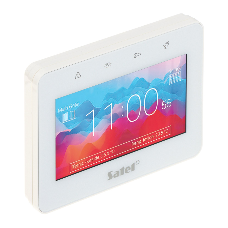
The screensaver on a keypad with factory default settings (Fig. 1) shows:
- date and time,
- the
![]() icon that indicates where to present the MIFARE card.
icon that indicates where to present the MIFARE card.
The installer can add to the screen additional widgets that will indicate the alarm system status (see "Widgets").
When the screensaver is displayed, you can:
- tap the screen to view the user screen,
- swipe left to start the slideshow.
Slideshow
If the screensaver has been disabled by the installer, the slideshow is not available.
The keypad can run a slideshow of images, if the installer installed in the keypad a memory card on which the images had been saved. When the slideshow is displayed, you can:
- tap the screen to view the user screen,
- swipe right to view the screensaver.
Trigger the panic alarm
When the screensaver or slideshow is displayed, tap the screen and hold for 3 seconds to trigger the panic alarm. The installer defines whether the alarm triggered will be loud (signaled by the alarm system) or silent (without signaling). The silent panic alarm is useful when the control panel reports events to the monitoring station, but unauthorized persons should not be aware of the alarm being triggered.
User screens
When the screensaver or slideshow is displayed, tap the screen to go to the user home screen.
If the screensaver has been disabled by the installer, the user home screen will be displayed when the keypad is not in use.
Only one user screen is available in the keypad with factory default settings. The installer can add more user screens and set one of them as the user home screen, i.e. one that is displayed first. Swipe left / right to go to another user screen (if more user screens were added by the installer). Information on which user screen is currently displayed is represented graphically on the bottom of the screen. See fig. 2

The user screen includes:
- status bar (see "Status bar"),
- widgets used to operate the alarm system, indicate the alarm system status, etc. (see "Widgets").
To run a function with a widget, you may be required to enter a code. If this is the case, the keypad will be displayed (see "On-screen keypad"). When you enter the code, the function will be run and you can be logged in. If you are already logged in, you will not be required to enter your code again when trying to run a function with a widget.
The following widgets are available on the user home screen in the keypad with factory default settings.
 | tap to fully arm the partitions operated by the keypad. |
 | tap to arm without interior the partitions operated by the keypad. |
 | tap to arm without interior and without entry delay the partitions operated by the keypad. |
 | tap to disarm the partitions operated by the keypad / clear alarm in them. |
 | tap and hold for 3 seconds to trigger the panic alarm. The installer defines whether the alarm triggered will be loud (signaled by the alarm system) or silent (without signaling). |
 | tap and hold for 3 seconds to trigger the fire alarm. |
 | tap and hold for 3 seconds to trigger the medical (auxiliary) alarm. |
 | tap to view the message. |
Consult the installer about which additional widgets may help you to operate the alarm system or control the home automation devices connected to the control panel. Only the installer can create new user screens, add widgets to the screen, etc.
The installer can configure the keypad so that the access to the user screen is codeprotected (a keypad will open before the screen is displayed).
Two different background pictures may be applied to user screens.
Additional screens
Additional screens differ from the user screens only in that each of them can have a different background picture. For this reason, the additional screens may be used to display site plans. If pictures other than the ones offered by SATEL are to be displayed, the installer must save them on a memory card and install the card in the keypad.
To display an additional screen, tap a link widget. See fig. 3

Status bar
The status bar is displayed on the top of the user screen and the additional screen.
It includes:
- screen title (optionally, if added by the installer),
- time,
- the
![]() icon. If you are not logged in, tap the icon to log in (keypad will open – see "On-screen keypad"). After you have logged in (entered the code), the user name will be displayed below the icon. If you are logged in, tap the icon to log out or go to the user menu.
icon. If you are not logged in, tap the icon to log in (keypad will open – see "On-screen keypad"). After you have logged in (entered the code), the user name will be displayed below the icon. If you are logged in, tap the icon to log out or go to the user menu.
Widgets
The widgets described below may be displayed on the screen.
Text
The widget displays any text that was added by the installer or system element name.
Partition state
The widget indicates the partition state by means of the following icons.
![]()
![]()
Zone state
The widget displays the zone state represented by either:
- icons selected by SATEL (indicator) – different states are displayed,
- text messages (text) – messages inform only about normal and violated states,
- icons selected by the installer (icon) – only normal and violated states are displayed.
The icons selected by SATEL are described in the table below.
![]()
![]()
Output state
The widget displays the output state represented by either:
- icons selected by SATEL (indicator),
- text messages (text),
- icons selected by the installer (icon).
The icons selected by SATEL are described in the table below.
![]()
Temperature
The widget displays the temperature. Information about the temperature is sourced from an ABAX 2 / ABAX wireless device.
Date/time
The widget displays the date and time in the format specified by the installer.
Switch
The icon for the widget is selected by the installer. Tap the widget to activate / deactivate an output.
Rectangle
The widget displays a rectangle that can be translucent and have different colors. As an additional graphic element it may be used e.g. to highlight a part of the screen.
Macro
The icon for the widget is selected by the installer. Tap the widget to run a macro command. The macro command is a sequence of actions to be performed by the control panel. Macro commands are created by the installer.
PANIC/FIRE/AUX.
The widget is used to trigger an alarm (  - panic alarm;
  - fire alarm;
  - medical alarm).
Information
The widget is represented on the screen by the  icon. Tap the widget to view the message prepared by the installer.
Link
The icon for the widget is selected by the installer. Tap the widget to go to the additional screen / return to the user screen from the additional screen.
Button
The icon for the widget is selected by the installer. The widget offers two functions:
- tap – tap the widget to turn on / off an output.
- tap and hold – tap and hold the widget to turn on an output. The output will remain on as long as you hold the widget. When you take your finger off the widget, the output will be turned off.
Analog value
The widget displays information on the power consumption of the appliance connected to the ASW-200 smart plug.
Thermostat
Depending on the thermostatic output state, the widget is represented on the screen by one of the icons:
 | first temperature threshold is active (temperature T1 – economy), output turned off, |
 | first temperature threshold is active (temperature T1 – economy), output turned on, |
 | second temperature threshold is active (temperature T2 – comfort), output turned off, |
 | second temperature threshold is active (temperature T2 – comfort), output turned on. |
Tap the widget to change the temperature settings for the thermostatic output.
The thermostatic output settings are used to adjust the operating parameters of the ART-200 wireless radiator thermostats.
On-screen keypad
The on-screen keypad is displayed when you are required to enter a code e.g. to access the user menu. You may be required to enter the code to access the user screen or the additional screen or to run a function with a widget. See Fig. 4

Enter the code using the number keys and tap  . If you made a mistake when entering the code, tap
  and re-enter the code (if you fail to enter the valid code within one minute, it will be treated as if you entered an invalid code).
If you tap before you enter the code, the on-screen keypad will close and you will return to the previous screen.
By default, the following codes are programmed in the control panel:
service code: 12345
object 1 master (administrator) code 1: 1111
If there is an alarm in the system, it will be cleared after you enter the code.
User menu
Swipe up on the user screen / additional screen to go to the user menu. Since the access to the user menu is code-protected, the keypad will open first. Enter the code. The menu will open immediately if you have already logged in on the user screen.
User menu home screen

The following functions are available on the user menu home screen. (Fig. 5)
 | tap to go to the "Partitions" screen. |
 | tap to go to the "Zones" screen. |
 | tap to go to the "Outputs" screen. |
 | tap to go to the "Troubles" screen. The function is available when a trouble is signaled by the alarm system. |
 | tap to go to the "Events" screen. |
 | tap to go to the "Users" screen. |
 | tap to go to the "Tests" screen. |
 | tap to go to the "Settings" screen. |
 | tap to go to the "Others" screen. |
If the icon is greyed out, the function is unavailable.
The ![]() icon displayed in the top right corner of the screen allows you to exit the user menu (same as the swipe down gesture).
icon displayed in the top right corner of the screen allows you to exit the user menu (same as the swipe down gesture).
QWERTY keyboard
The QWERTY keyboard is used to enter text. It is displayed when you search for items on certain screens, enter user names, etc. See figs. 6-7


The text entered is displayed in the field above the keys.
In addition to the typing keys, the following special keys are available.
 | tap to switch the keyboard to the uppercase mode. |
 | tap to switch the keyboard to the lowercase mode. |
 | tap to exit the QWERTY keyboard. |
 | tap to switch the keyboard to the number keys mode. |
 | tap to switch the keyboard to the letter keys mode. |
 | tap to delete the character before the cursor. |
 | tap to enable / disable the diacritical marks mode. |
 | tap to confirm the text entered. |
Terminal
The terminal allows you to enter data and configure the settings in the same way as from the LCD keypad with text menu (  acts as #;
  acts as
 ![]() ). It is displayed if you run certain user functions or service functions. See Fig. 8
). It is displayed if you run certain user functions or service functions. See Fig. 8

Data editing by using the terminal
The editing method depends on the type of data. Having completed the editing, tap to save the changes. If you want to exit the function without saving the changes, tap .
Selection from the single-choice list
In the lower line of the display, the currently selected item is presented. You can scroll the list using the  and
and  keys.
keys.
Selection from the multiple-choice list
In the lower line of the display, one of the items you can choose from is presented. You can scroll the list using the and keys. The following character is displayed in the upper line:
Y – displayed item is selected / option is enabled,
. – displayed item is not selected / option is disabled.
Tap any number key to change the currently shown character for another one.
Entering decimal and hexadecimal values
To enter digits, use the number keys. To enter characters from A to F, use the  and
and  keys (keep tapping the key until the required character appears).
Entering names
Keep tapping the key until the required character appears. Long tap the key to display the digit assigned to it.
Shown on the left side in the upper line of the display is information about the letter case:
[Abc], [ABC] or [abc] (it is shown for a few seconds when you tap any key). Tap to change the letter case.
The  key moves the cursor to the right, and the
  key – to the left. The
  key deletes the character on the left side of the cursor.
Partitions screen
On this screen you can see the list of the partitions that you can operate by means of the keypad. The partitions are represented by icons that indicate the partition state. The icons are the same as the ones used by the "Partition state" widget. The partition name may be displayed beside the icon. See Fig. 9

The icons in the top right corner allow you to:
| The icons in the top right corner allow you to: | |
 | tap to clear alarm. |
 | tap to terminate the exit delay (function available if the installer enabled the exit delay clearing). |
 | tap to filter the partition list (see "Filtering the partition list"). |
 | tap to search for partition/partitions (see "Searching for partitions"). |
 | tap to go back to the user menu home screen. |
| The icon displayed in front of the object name allows you to: | |
 | tap to hide the list of partitions that belong to the object. |
 | tap to show the list of partitions that belong to the object. |
Information about how many partitions are selected is shown in brackets next to the partition name ([number of selected partitions]/[number of partitions]).
The numbers displayed next to the following icons indicate:
 | number of disarmed partitions where zones are violated. |
 | number of armed partitions. |
| number of partitions where alarm condition occurs. |
 | number of partitions where exit delay is running. |
 | number of partitions where the first code has been entered (the partition is armed / disarmed using two codes). |
If you tap the screen close to the bottom edge and swipe up, the buttons with the icons will appear at the bottom of the screen:
 | tap to increase the size of the icons/names on the list. |
 | tap to decrease the size of the icons/names on the list. |
 | tap to hide the partition names on the list. |
 | tap to display the partition names on the list. |
| tap to hide the buttons. |
Arming
- Tap the partition you want to arm. The button with the
![]() icon will appear at the bottom of the screen (if the button with the
icon will appear at the bottom of the screen (if the button with the ![]() icon will appear, it means that the partition is armed using two codes – see "Two-code arming").
icon will appear, it means that the partition is armed using two codes – see "Two-code arming"). - If you want to arm several partitions, tap each partition one by one.
- Tap the button with the
![]() icon. The buttons with available arming modes will appear.
icon. The buttons with available arming modes will appear. - Tap the button with the arming mode you want to activate.
- Tap the button with the
![]() icon. The arming procedure will start.
icon. The arming procedure will start.
 icon will appear, it means that the partition is armed using two codes – see "Two-code arming").
 icon. The arming procedure will start.
Two-code arming
When two users are required in order to arm a partition, follow these steps:
- Tap the partition you want to arm. The button with the
![]() icon will appear at the bottom of the screen.
icon will appear at the bottom of the screen. - If you want to arm several partitions that require 2 codes for arming, tap each partition one by one.
- Tap the button with the
![]() icon. The buttons and the slider will appear at the bottom of the screen.
icon. The buttons and the slider will appear at the bottom of the screen. - If the installer did not set the code validity time to 30 seconds, you can set the code expiration time using the slider.
- Tap the button with the
![]() icon.
icon. - Ask another user to arm the partition. The same keypad (see "Arming") or another keypad can be used for this purpose as well as a partition keypad or a proximity card reader.
The installer can configure the alarm system so that the same keypad cannot be used to enter the second code.
Disarming
- Tap the partition you want to disarm. The button with the
![]() icon will appear at the bottom of the screen (if the button with the
icon will appear at the bottom of the screen (if the button with the ![]() icon will appear, it means that the partition is disarmed using two codes – see "Two-code disarming").
icon will appear, it means that the partition is disarmed using two codes – see "Two-code disarming"). - If you want to disarm several partitions, tap each partition one by one.
- Tap the button with the
![]() icon.
icon.
 icon will appear at the bottom of the screen (if the button with the
  icon will appear, it means that the partition is disarmed using two codes – see "Two-code disarming").
 If there was an alarm condition in the partition, disarming will clear the alarm.
Two-code disarming
When two users are required to enter the code in order to disarm a partition, follow these steps:
- Tap the partition you want to disarm. The button with the
![]() icon will appear at the bottom of the screen.
icon will appear at the bottom of the screen. - If you want to disarm several partitions that require 2 codes for disarming, tap each partition one by one.
- Tap the button with the
![]() icon. The buttons and the slider will appear at the bottom of the screen.
icon. The buttons and the slider will appear at the bottom of the screen. - If the installer did not set the code validity time to 30 seconds, you can set the code expiration time using the slider.
- Tap the button with the
![]() icon.
icon. - Ask another user to disarm the partition. The same keypad (see "Disarming") or another keypad can be used for this purpose as well as a partition keypad or a proximity card reader.
The installer can configure the alarm system so that the same keypad cannot be used to enter the second code.
Cancelling the first code
If you entered the first code while two-code arming / disarming, you can cancel it by following these steps:
- Tap the partition where you want to cancel the first code. The button with the
![]() icon will appear at the bottom of the screen.
icon will appear at the bottom of the screen. - If you want to cancel the first code in several partitions, tap each partition one by one.
- Tap the button with the
![]() icon. The buttons will appear at the bottom of the screen.
icon. The buttons will appear at the bottom of the screen. - Tap the button with the
![]() icon.
icon.
 icon.
icon.Auto-arming deferment
If the auto-arm delay countdown is programmed for the partition, you can defer the auto-arm in the partition. This function is useful for partitions that are armed by the timer.
- Tap the partition where you want to defer the auto-arm. The button with the
![]() icon will appear at the bottom of the screen.
icon will appear at the bottom of the screen. - If you want to defer the auto-arm in several partitions, tap each partition one by one.
- Tap the button with the
![]() icon. The slider for setting the time will appear.
icon. The slider for setting the time will appear. - Set the time using the slider.
The maximum time period for which you can defer the auto-arm is different when the auto-arm delay is running and different when it is not.
- Tap the button with the
![]() icon.
icon.
Filtering the partition list
- Tap the
![]() icon. The buttons with filtering criteria will appear.
icon. The buttons with filtering criteria will appear. - Tap the buttons with the filtering criteria that you want to use. You can tap any number of buttons.
- Tap the button with the
![]() icon. The partitions that meet the selected criteria will be displayed.
icon. The partitions that meet the selected criteria will be displayed.
Searching for partitions
- Tap the
![]() icon. The QWERTY keyboard will appear.
icon. The QWERTY keyboard will appear. - Enter a string of characters that is to be included in the partition / partitions name.
- Tap the button with the
![]() icon. Partitions whose name includes the entered string of characters will be displayed.
icon. Partitions whose name includes the entered string of characters will be displayed.
Zones screen
On this screen you can see the list of zones belonging to the partitions that you can operate by means of the keypad. The zones are represented by icons that indicate the zone state.
The icons are the same as the ones used by the "Zone state" widget in the indicator mode (see "Zone state"). The zone name may be displayed beside the icon. See Fig. 10.

| The icons in the top right corner allow you to: | |
 | tap to filter the zone list (see "Filtering the zone list"). |
 | tap to search for zone/zones (see "Searching for zones"). |
 | tap to go back to the user menu home screen. |
| The icon displayed in front of the partition name allows you to: | |
| tap to hide the list of zones that belong to the partition. |
| tap to show the list of zones that belong to the partition. |
Information about how many zones are selected is shown in brackets next to the partition name ([number of selected zones]/[number of zones]).
The numbers displayed next to the following icons indicate:
 | number of zones in normal state. |
 | number of violated zones. |
| | number of zones that triggered alarm. |
 | number of bypassed zones. |
 | number of tampered zones. |
If you tap the screen close to the bottom edge and swipe up, the buttons with the icons will appear at the bottom of the screen:
| tap to increase the size of the icons/names on the list. |
| tap to decrease the size of the icons/names on the list. |
 | tap to hide the zone names on the list. |
 | tap to display the zone names on the list. |
| tap to hide the buttons. |
Zone inhibiting
The inhibited zone will remain bypassed until disarming the partition it belongs to, or until unbypassing the zone by the user.
- Tap the zone you want to inhibit. The button with the
![]() icon will appear at the bottom of the screen.
icon will appear at the bottom of the screen. - If you want to inhibit several zones, tap each zone one by one.
- Tap the button with the
![]() icon.
icon.
Zone isolating
The isolated zone will remain bypassed until unbypassed by the user.
- Tap the zone you want to isolate. The button with the
![]() icon will appear at the bottom of the screen.
icon will appear at the bottom of the screen. - If you want to isolate several zones, tap each zone one by one.
- Tap the button with the
![]() icon.
icon.
Zone unbypassing
- Tap the zone you want to unbypass. The button with the
![]() icon will appear at the bottom of the screen.
icon will appear at the bottom of the screen. - If you want unbypass several zones, tap each zone one by one.
- Tap the button with the
![]() icon.
icon.
Filtering the zone list
- Tap the
![]() icon. The buttons with filtering criteria will appear.
icon. The buttons with filtering criteria will appear. - Tap the buttons with the filtering criteria that you want to use. You can tap any number of buttons.
- Tap the button with the
![]() icon. The zones that meet the selected criteria will be displayed.
icon. The zones that meet the selected criteria will be displayed.
Searching for zones
- Tap the
![]() icon. The QWERTY keyboard will appear.
icon. The QWERTY keyboard will appear. - Enter a string of characters that is to be included in the zone / zones name.
- Tap the button with the
![]() icon. Zones whose name includes the entered string of characters will be displayed.
icon. Zones whose name includes the entered string of characters will be displayed.
Outputs screen
On this screen you can see the list of outputs in the system. The outputs are represented by icons that indicate the output state. The icons are the same as the ones used by the "Output state" widget in the indicator mode (see "Output state"). The output name may be displayed beside the icon.
The icon is displayed in the top right corner of the screen. Tap it to go back to the user menu home screen.
The icon displayed in front of the name of the outputs group allows you to:
| tap to hide the list of outputs that belong to the group. |
| tap to show the list of outputs that belong to the group. |
Information about how many outputs are activated is shown in brackets next to the group name ([number of activated outputs]/[number of outputs]).
If you tap the screen close to the bottom edge and swipe up, the buttons with the icons will appear at the bottom of the screen:
| tap to increase the size of the icons/names on the list. |
| tap to decrease the size of the icons/names on the list. |
 | tap to hide the output names on the list. |
 | tap to display the output names on the list. |
| tap to hide the buttons. |
Output control
Tap the controllable output to change its state. The controllable outputs are the outputs programmed as "MONO switch" / "BI switch" / "Remote switch" / "Shutter up" / "Shutter down". You can recognize these outputs by the icon (see description of the "Output state" widget).
Troubles screen
On this screen you can see the list of troubles. The installer defines whether only the current troubles are to be presented, or also those which have already ended (trouble memory).
Each trouble poses a danger to proper functioning of the alarm system and should be repaired as soon as possible. If necessary, consult the installer.
The icons in the top right corner allow you to:
 | tap to clear the trouble memory. |
| tap to go back to the user menu home screen. |
Events screen
On this screen you can see the list of events. Events are displayed in order from the most recent to the oldest.
The icons in the top right corner allow you to:
 | tap to display events required by the EN 50131 standard for Grade 3 / Grade 2. |
 | tap to filter the event list by partitions (see "Filtering the event list by partitions"). |
| tap to filter the event list by types (see "Filtering the event list by types"). |
 | tap to display the event descriptions in colors (different colors for different event types). |
| tap to go back to the user menu home screen. |
Filtering the event list by partitions
- Tap the
![]() icon. The "Partition" screen will be displayed.
icon. The "Partition" screen will be displayed. - Tap the names of the partitions from which you want to view events.
- Tap the
![]() icon in the top right corner of the screen. The events from the selected partitions will be displayed.
icon in the top right corner of the screen. The events from the selected partitions will be displayed.
Filtering the event list by types
- Tap the
![]() icon. The buttons with filtering criteria will appear.
icon. The buttons with filtering criteria will appear. - Tap the buttons with the filtering criteria that you want to use. You can tap any number of buttons.
- Tap the button with the
![]() icon. The events that meet the selected criteria will be displayed.
icon. The events that meet the selected criteria will be displayed.
Users screen
On this screen you can see the list of users. The icon displayed below the user name provides additional information about the user. The icons are described in the table below.
If you enter the service code, the administrators will be displayed on the screen as well as the users. All actions that you can perform for the users are also available for the administrators.
| Icon | Status |
 | user requires no attention |
 | "Scheduled" type user has no access to the system (tap the user name to obtain additional information) |
 | user should change the code / telephone code / prefix (tap the user name to obtain additional information) |
The numbers displayed next to the following icons indicate:
 | number of users who require no attention. |
 | number of users who have no access to the system. |
| number of users who should change the code / telephone code / prefix. |
The icons in the top right corner allow you to:
| tap to add a new user (see "Adding a user"). |
 | tap to remove the user/administrator (see "Removing a user"). The icon appears when you select a user. |
 | tap to edit the user (see "Editing a user"). The icon appears when you select a user. |
| tap to search for user/users (see "Searching for users"). |
 | tap to go back to the user menu home screen. |
Adding a user
- Tap the
![]() icon. The buttons will appear at the bottom of the screen.
icon. The buttons will appear at the bottom of the screen. - Tap the button with the
![]() icon. The user settings panel will appear.
icon. The user settings panel will appear. - Configure the user settings.
- Tap the "Save" button. A message will be displayed to confirm that the user data were saved.
- Tap the "Close" button. The user settings panel will close.
Removing a user
- Tap the user you want to remove.
- Tap the
![]() icon. The buttons will appear at the bottom of the screen.
icon. The buttons will appear at the bottom of the screen. - Tap the button with the
![]() icon.
icon.
Editing a user
- Tap the user whose settings you want to edit.
- Tap the
![]() icon. The user settings panel will appear.
icon. The user settings panel will appear. - Change the user settings.
- Tap the "Save" button. A message will be displayed to confirm that the user data were saved.
- Tap the "Close" button. The user settings panel will close.
Searching for users
- Tap the
![]() icon. The QWERTY keyboard will appear.
icon. The QWERTY keyboard will appear. - Enter a string of characters that is to be included in the user / users name.
- Tap the button with the
![]() icon. Users whose name includes the entered string of characters will be displayed.
icon. Users whose name includes the entered string of characters will be displayed.
Tests screen

The following functions can be displayed on the screen(fig. 12):
Supply voltages – tap to check the supply voltage of the control panel mainboard and the modules. The function available to the installer.
Radio devices – tap to check the radio signal level of wireless devices.
Temperatures – tap to check the temperature (temperature information is provided by the ABAX 2 / ABAX wireless devices).
Battery test – tap to check the status of batteries of the control panel and expansion modules with power supply and the status of "60. Tech.-Battery low" type zones. Upon starting the function, the control panel will generate events that you can see on the "Events" screen. The function available to the installer.
Manual tr. test – tap to generate an event that starts the procedure of event transmission to the monitoring station (a code sent with the system identifier).
Station 1A test / Station 1B test / Station 2A test / Station 2B test – tap to send a test transmission to the monitoring station (separate function for each of the telephone numbers). When sending the transmission, messages are displayed to inform about the currently performed operation.
GPRS monit.test – tap to send a test transmission to the monitoring station via cellular data network. When sending the transmission, messages on the display provide information on the currently performed operation.
Messaging test – tap to test the telephone messaging (see "Messaging test").
Answering test – tap to test the answering phone calls by the control panel (information on the number of rings and going off-hook will be displayed).
CA-64 PTSA test – tap to test the mimic board.
View masters – tap to check in which objects the master users are created.
Keypad name – tap to see the keypad name.
File in DLOADX – tap to see the date and time of writing the data to the control panel by means of the DLOADX program and the name of file with control panel data.
Panel version – tap to display information on the control panel firmware version.
STM prg.version – tap to display information on the program version of the processor used to operate the zones / ABAX system.
GSM IMEI/v/sig. – tap to display the information on the level of GSM signal, IMEI number and version of the telephone. The function available in the INTEGRA 128-WRL control panel.
IP/MAC/IMEI/ID – tap to display the information related to the ETHM-1 Plus / ETHM-1 / INT-GSM modules.
Modules versions – tap to display the information on the firmware versions of devices connected to the control panel communication buses.
Burglary zones – tap to test the burglary zones (see "Burglary / fire / technical zone test").
Fire/tech. zones – tap to test the fire and technical zones (see "Burglary / fire / technical zone test").
One zone – tap to test the selected zone (see "Selected zone test").
Finish test – tap to end the zone test.
View results – tap to see the zone test results (see "Review of test results").
Clear results – tap to clear the zone test results.
The terminal will appear upon tapping most of the functions (see "Terminal").
The ![]() icon is displayed in the top right corner of the screen. Tap it to go back to the user menu home screen.
icon is displayed in the top right corner of the screen. Tap it to go back to the user menu home screen.
Messaging test
- Tap the "Messaging test" function. The terminal will be displayed.
- Enter the consecutive number of the phone to be notified.
- Tap
![]() .
. - Enter the consecutive number of the voice message to be played back.
- Tap
![]() . The control panel will call the selected number and play back the message.
. The control panel will call the selected number and play back the message.
 .
. . The control panel will call the selected number and play back the message.
Burglary/fire/technical zone test
- Tap the "Burglary zones" / "Fire/tech. zones" function. The terminal will be displayed.
- Select the partitions in which you want to test zones. You can scroll the partition list using the
![]() or
or ![]() key. If you want to test zones in the partition, tap any number key (the following character will be displayed next to the partition name: Y).
key. If you want to test zones in the partition, tap any number key (the following character will be displayed next to the partition name: Y). - Tap
![]() .
. - Specify the test duration (maximum 50 minutes) and tap
![]() .
. - Define, whether violation of a zone is to trigger CHIME in the keypad (if yes, tap any number key – the following character will be displayed: Y).
- Tap
![]() . The zone test will start.
. The zone test will start.
 or
or  key. If you want to test zones in the partition, tap any number key (the following character will be displayed next to the partition name: Y).
 .
. Starting the zone test will enable the test mode in all ABAX 2 / ABAX system wireless devices (the wireless detectors will indicate violations by means of LEDs).
- Depending on the type of tested detector:
- magnetic contact – open and close the door or window protected by the magnetic contact,
- motion detector – walk through the coverage area of the detector,
- other detectors – follow the manufacturer's directions for the detector testing.
- Tap the "View results" function to see the test results (see "Review of test results").
- Tap the "Clear results" function to delete the test results.
Selected zone test
- Tap the "One zone" function. The terminal will be displayed.
- Select the zone you want to test. You can scroll the zone list using the
![]() or
or ![]() key.
key. - Tap
![]() .
. - Specify the test duration (maximum 50 minutes) and tap
![]() .
. - Define, whether violation of the zone is to trigger CHIME in the keypad (if yes, tap any number key – the following character will be displayed: Y).
- Tap
![]() . The zone test will start.
. The zone test will start. - Depending on the type of tested detector:
- magnetic contact – open and close the door or window protected by the magnetic contact,
- motion detector – walk through the coverage area of the detector,
- other detectors – follow the manufacturer's directions for the detector testing.
- Tap the "View results" function to see the test results (see "Review of test results").
- Tap the "Clear results" function to delete the test results.
Review of test results
Tap the "View results" function. The list of tested zones will be displayed. The icon that indicates the test results is displayed below the zone name:
 | zone was not violated. |
 | zone was violated. |
Information about the status of the tested zones is not refreshed automatically. If you want to refresh the information, tap the "View results" function again.
Settings screen
The functions that can be available on the "Settings" screen are described below (Fig. 13).


The terminal will appear upon tapping most of the functions (see "Terminal").
The ![]() icon is displayed in the top right corner of the screen. Tap it to go back to the user menu home screen.
icon is displayed in the top right corner of the screen. Tap it to go back to the user menu home screen.
Keypad screen
The functions available on the "Keypad" screen are described below (Fig. 14).

 | tap to set the screen brightness (see "Setting the screen brightness"). |
 | tap to set the keypad volume (see "Setting the keypad volume"). |
 | tap to lock the touch screen for 30 seconds. It will allow you to clean the screen. |
 | tap to update the keypad firmware (see the keypad installer manual). |
 | tap to format the memory card. |
 | tap to set the auto logout time (see: "Setting the auto logout time"). |
Tap  in the top right corner of the screen to return to the previous screen.
Setting the screen brightness
Tap the "Brightness" function. The sliders and the buttons will appear at the bottom of the screen. The sliders are marked with the icons described in the table below.
 | screen brightness in the daytime when the keypad screen is woken up. |
 | screen brightness in the daytime when the keypad is not used. |
 | beginning of the daytime. |
 | screen timeout in the daytime (if you set 0, the screen will not be turned off). |
 | screen brightness in the nighttime when the keypad screen is woken up. |
 | screen brightness in the nighttime when the keypad is not used. |
 | beginning of the nighttime. |
 | screen timeout in the nighttime (if you set 0, the screen will not be turned off). |
Tap the button with the ![]() icon to confirm changes. Tap the button with the
icon to confirm changes. Tap the button with the ![]() icon to cancel changes.
icon to cancel changes.
Setting the keypad volume
Tap the "Loudness" function. The sliders and the buttons will appear at the bottom of the screen. The sliders are marked with the icons described in the table below.
 | volume of the sounds generated when using the keypad (tapping the screen). |
 | volume of the CHIME sounds (signaling of zone violation). |
 | volume of the entry delay sounds. |
 | volume of the exit delay sounds. |
 | volume of the fire alarm sounds. |
 | volume of the alarm sounds. |
Tap the button with the ![]() icon to confirm changes. Tap the button with the
icon to confirm changes. Tap the button with the ![]() icon to cancel changes.
icon to cancel changes.
Setting the auto logout time
Tap the „Auto logout" function. The buttons and the slider will appear at the bottom of the screen. Use them to set the time of inactivity after which the user will be automatically logged out. Tap the button with the ![]() icon to confirm changes. Tap the button with the
icon to confirm changes. Tap the button with the ![]() icon to cancel changes.
icon to cancel changes.
The auto logout time is also used to set the time of inactivity after which the screensaver will be displayed (if it is enabled).
When the service menu is displayed, the auto logout and screensaver functions are disabled.
Others screen
The functions available on the "Others" screen are described below (Fig. 15).


Tap ![]() in the top right corner of the screen to return to the previous screen.
in the top right corner of the screen to return to the previous screen.
Downloading screen
The following functions can be displayed on the screen:
Start DWNL-RS – tap if you want to enable the local programming of the control panel using the DLOADX program (computer with DLOADX program connected to the RS-232 / USB port of the control panel). The function available to the installer.
Finish DWNL-RS – tap if you want to disable the local programming of the control panel using the DLOADX program. The function available to the installer.
Start DWNL-MOD. – tap when you want to start the communication with the DLOADX program via the external modem (analog, GSM or ISDN).
Start DWNL-TEL – tap when you want to start the communication with the DLOADX program via the 300 bps modem.
Start DWNL-CSD – tap when you want to start the CSD communication with the DLOADX program via the control panel GSM communicator. The function available in the INTEGRA 128-WRL control panel.
Start DWNL-GPRS – tap when you want to start the GPRS communication with the DLOADX program via the control panel GSM communicator. The function available in the INTEGRA 128-WRL control panel.
ETHM-1 >DLOADX – tap when you want to start the communication with the DLOADX program via the ETHM-1 / ETHM-1 Plus module. The communication will be via Ethernet. If the INT-GSM module is connected to the ETHM-1 Plus module and an attempt to establish communication via Ethernet fails, an attempt will be made to establish communication via the cellular data network.
ETHM-1 >GUARDX – tap when you want to start the communication with the GUARDX program via the ETHM-1 / ETHM-1 Plus module. The communication will be via Ethernet. If the INT-GSM module is connected to the ETHM-1 Plus module and an attempt to establish communication via Ethernet fails, an attempt will be made to establish communication via the cellular data network.
INT-GSM >DLOADX – tap when you want to start the communication with the DLOADX program via the INT-GSM module. The communication will be via the cellular data network.
INT-GSM >GUARDX – tap when you want to start the communication with the GUARDX program via the INT-GSM module. The communication will be via the cellular data network.
Service menu
On this screen you can see the service functions. Tap the function to view the list of other functions, parameters or options. If you tap the parameter name, the terminal will appear to enable you to edit data (see "Terminal"). If you tap the option name, the option will be enabled (the following character will be displayed next to the option name: Y) or disabled (the following character will be displayed next to the option name: .). See fig. 16.

The icons in the top right corner allow you to:
 | tap to display/hide the terminal (the terminal allows you to use the service menu in the same way as from the LCD keypad with text menu). |
 | tap to return to the previous list in the service menu. |
For details on how to configure the control panel, see the control panel programming manual.
Tap "End service" function to exit the service menu.
SATEL sp. z o.o. • ul. Budowlanych 66 • 80-298 Gdańsk • POLAND tel.
+48 58 320 94 00
www.satel.pl
Documents / Resources
References
Download manual
Here you can download full pdf version of manual, it may contain additional safety instructions, warranty information, FCC rules, etc.
Download Satel INTEGRA, INT-TSG2R, INT-TSG2R-W, INT-TSG2R-B - Keypad Manual
Advertisement


Need help?
Do you have a question about the INTEGRA and is the answer not in the manual?
Questions and answers