Satel INT-TSG Installer Manual
Hide thumbs
Also See for INT-TSG:
- Installer manual (28 pages) ,
- User manual (21 pages) ,
- Quick user manual (11 pages)

Related Manuals for Satel INT-TSG


Summary of Contents for Satel INT-TSG
- Page 1 10/13 Keypad INT-TSG Installer Manual Firmware version 1.00 SATEL sp. z o.o. • ul. Schuberta 79 • 80-172 Gdańsk • POLAND tel. 58 320 94 00 • info@satel.pl www.satel.eu...
- Page 2 Changes, modifications or repairs not authorized by the manufacturer shall void your rights under the warranty. The SATEL's goal is to continually upgrade the quality of its products, which may result in alterations of their technical specifications and firmware. The current information on the introduced modifications is available on our website.
-
Page 3: Installation And Hook-Up
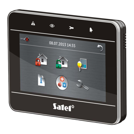
Tamper contact reacting to the enclosure opening or detaching from the wall. 2. Installation and hook-up Disconnect power before making any electrical connections. The INT-TSG keypad is designed for indoor installation. The place of installation should be readily accessible to the system users. 1. Open the keypad enclosure (see Fig. 1). - Page 4 INT-TSG SATEL Fig. 1. Opening the enclosure. 2.1 Description of terminals - power supply input. - common ground. - data. - clock. A RS485 B - unused terminals. - zones. Z1, Z2...
- Page 5 SATEL INT-TSG Fig. 2. Connection of the keypad to the control panel. 3. Addressing The keypad must have an individual address set in it: from the 0 to 3 range, if it is connected to the INTEGRA 24 or INTEGRA 32 control panel;...
-
Page 6: Keypad Identification
X program (”Structure” window ”Hardware” tab ”Keypads” item ”Keypads LOAD identification” button). The procedure of entering the service mode by means of the INT-TSG keypad is described in section „Programming keypad address by means of service function” (p. 3). 5. microSD memory card On the microSD memory card: ... -
Page 7: Keypad Configuration
LOAD name). The procedure of entering the service mode by means of the INT-TSG keypad is described in section „Programming keypad address by means of service function” (p. 3). Creating the macro commands and configuring the status screen is only possible in the X program. - Page 8 INT-TSG SATEL Partitions managed by keypad [Partitions] – the partitions which can be armed/disarmed or alarm in which may be cleared from the keypad. These functions are available to the users having a suitable authority level and access to those partitions.
- Page 9 SATEL INT-TSG Fig. 4. Keypad parameters and options in D X program. LOAD Signaling entry delay [Entry time s.] – with this option enabled, the keypad will audibly signal the entry delay countdown. Signaling exit delay [Exit time sig.] – with this option enabled, the keypad will audibly signal the exit delay countdown.
- Page 10 INT-TSG SATEL Signaling troubles in partially arm [Trbl. in p.arm.] – with this option enabled, the keypad signals troubles by means of the LED, if some of the operated partitions are armed (the troubles are not signaled if all partitions are armed).
- Page 11 SATEL INT-TSG Fig. 5. „Volume/filter” tab, D X program. LOAD 6.3 State inspections Fig. 6. "State inspections” tab, D X program. LOAD Inspection – you can select functions which will be available without using the code: – on the "System status" screen;...
-
Page 12: Macro Commands
INT-TSG SATEL – after touching for about 3 seconds of the corresponding key, designated with a digit in the case of the terminal. Zone state [Zone characters] – you can define the symbols which will be used by the terminal to illustrate the state of zones. - Page 13 SATEL INT-TSG Fig. 7. “Groups” tab, D X program. LOAD Name – name of the macro command group which is displayed on the keypad screen under the icon (up to 8 characters). Do not enter the name if it is not to be displayed.
- Page 14 INT-TSG SATEL 6.5.2 Definitions Fig. 8. "Definitions” tab, D X program. LOAD You can create and configure macro commands in the "Definitions" tab. The macro command is a sequence of actions, composed of single commands, which are to be done by the control panel when running the macro command.
- Page 15 SATEL INT-TSG No confirmation messages – if this option is enabled, no messages will appear to inform you about execution of a command or an error after running a macro command (the screen from which the macro command was run will still be displayed).
- Page 16 INT-TSG SATEL Group address – the group address which will be inserted in the telegram. Type – the telegram type. Value – the value that will be inserted in the telegram (parameter available for some types of the telegram). Priority – telegram priority (if two elements of the bus start transmitting simultaneously, the telegram with higher priority will be sent first).
-
Page 17: Status Screen
SATEL INT-TSG 16. Click the "Groups" tab”. 17. Click the group to be edited. 18. Enter the group name, if it is to be displayed on the keypad. 19. Select the icon which will be used to present the group of macro commands on the keypad (provided a microSD card is installed in the keypad) or leave the default icon. - Page 18 INT-TSG SATEL The status screen is displayed automatically after the keypad is idle for 60 seconds. This rule does not apply if the terminal is running. In such a case, the status screen may be displayed later or even will not be displayed at all (e.g. when the service menu is open). The following information can be displayed on the status screen: –...
- Page 19 SATEL INT-TSG R2 = 1,1 k. The resistor value for Single EOL configuration is the sum of R1 and R2 resistors. INTEGRA Plus: parameters of the EOL resistors should be defined for the mainboard zones. The same parameters will be set automatically for the zones in keypads in which the value of EOL resistors is programmable.
-
Page 20: Specifications
INT-TSG SATEL 11. Within 10 seconds, touch any part of the screen to start the firmware updating (if you do not touch the screen, the firmware will not be updated, but the file with the new firmware version will be erased from the microSD card and the keypad restart will follow).
Need help?
Do you have a question about the INT-TSG and is the answer not in the manual?
Questions and answers