
Related Manuals for ADLINK Technology HPERC-KBL-MC


Summary of Contents for ADLINK Technology HPERC-KBL-MC
- Page 1 HPERC-KBL-MC/MH High Performance Extreme Rugged Computer System User’s Manual Manual Rev.: September 28, 2021 Rev. Date: Part Number: 50M-00048-1010 Leading EDGE COMPUTING...
- Page 2 Revision History Revision Description of Changes Release Date Initial release 2020-03-02 Add MXM-T1000 MXM module; update specifiations and pin 2021-09-28 definitions Revision History...
-
Page 3: Preface
HPERC-IBR-H Preface Copyright © 2020, 2021 ADLINK Technology Inc. This document contains proprietary information protected by copyright. All rights are reserved. No part of this manual may be reproduced by any mechanical, electronic, or other means in any form without prior written permission of the manufacturer. - Page 4 Trademarks Product names mentioned herein are used for identification purposes only and may be trade- marks and/or registered trademarks of their respective companies. Conventions Take note of the following conventions used throughout this manual to make sure that users perform certain tasks and instructions properly. Additional information, aids, and tips that help users perform tasks.
-
Page 5: Table Of Contents
HPERC-KBL-M Table of Contents Revision History ..................ii Preface ....................iii List of Figures ..................vii List of Tables ..................ix 1 Introduction..................1 About the HPERC-KBL-M................1 Using this Guide ..................1 Requirements ..................... 1 Specifications..................... 2 Block Diagram.................... 4 Power Specifications................. - Page 6 3.2.10 System Date and Time.................. 30 Advanced....................31 3.3.1 CPU Configuration ..................31 3.3.2 Power & Performance................... 32 3.3.3 PCH-FW Configuration ................. 33 3.3.4 Trusted Computing ..................33 3.3.5 NCT6106D Super IO Configuration.............. 34 3.3.6 NCT5104DSEC Super IO Configuration ............36 3.3.7 Serial Port Console Redirection ..............
-
Page 7: List Of Figures
HPERC-KBL-M List of Figures Figure 1-1: HPERC-KBL-M Block Diagram ................4 Figure 1-2: HPERC-KBL-M Unit with Optional Accessories ..........6 Figure 2-1: Top and Front Views of “MH” Enclosure with Mounting Dimensions ....8 Figure 2-2: Top and Front Views of “MC” Enclosure with Mounting Dimensions ....9 Figure 2-3: Bottom View of “MC”... - Page 8 This page intentionally left blank. viii List of Figures...
-
Page 9: List Of Tables
HPERC-KBL-M List of Tables Table 1-1: HPERC-KBL-M Specifications ................2 Table 1-2: System Power Requirements ................5 Table 2-1: I/O Panel Connectors ..................13 Table 2-2: DB9 Male Connector Pin Definition..............14 Table 2-3: GPIO Breakout Wires..................14 Table 2-4: P2 Connector Pin Definitions and Signal Maps..........16 Table 2-5: P3 Connector Pin Definitions and Signal Maps.......... - Page 10 This page intentionally left blank. List of Tables...
-
Page 11: Introduction
HPERC-KBL-M 1 Introduction 1.1 About the HPERC-KBL-M The HPERC products are intended for users of embedded systems requiring long life-cycles, configuration control, and ruggedness in hardened military packages. HPERC models feature Extreme Rugged computer boards available with varieties of processors and memory. An optional operating system (OS) can be pre-loaded onto an optional internal storage device (two 2.5"... -
Page 12: Specifications
1.4 Specifications Table 1-1: HPERC-KBL-M Specifications VITA 75 VITA Standards • Form Factor: VITA-75.22 Conductive Cold Plate • Dimensions: 223.65(L) x 177.80(W) x 98.70(H) mm (with mounting brackets) • Weight: 4.7kg Mechanical • Form Factor: VITA-75 Finned Passive Convection • Dimensions: 304.80(L) x 150.00(W) x 129.95(H) mm (with mounting brackets) •... - Page 13 HPERC-KBL-M Table 1-1: HPERC-KBL-M Specifications MC: Cold plate conduction, VITA 75.22 mount • CPU Only: -40°C to +85°C at cold plate* • With MXM-P1000/P2000: -40°C to +74°C at cold plate* • With MXM T1000: -40°C to +71°C at cold plate* *Note: Dependent on an external thermal solution design that maintains the temperature at Operating any point on the cold plate surface within the indicated temperature range.
-
Page 14: Block Diagram
1.5 Block Diagram DDR4 2133MHz PCIe x16 Link Intel® Xeon® Connector Processor E3-1505M v6 DDR4 2133MHz PCI-32bit XIO2001 33/66MHz PEX 8618 PCIe-to-PCI PCIe x1 PCIe Bridge Switch (1 & 2) PCIe x1 Mini-PCIe 6x SATA slot PCIe x4 2x DVI-D 2x PCIe x4 PCIe x4 4x PCIe x1... -
Page 15: Power Specifications
HPERC-KBL-M 1.6 Power Specifications Table 1-2 lists the current and power draw of the HPERC-KBL-M, featuring the Intel® Xeon® Processor E3-1505M v6 (3.00GHz). Input power is +24 VDC regulated. Table 1-2: System Power Requirements Parameter Current (Power) Idle 1.1A (26.4W) (Windows 10) Intel TA tool @100% 3.16A (75.9W) -
Page 16: What's In The Box
Check the items in the shipping box for the HPERC-KBL-M Unit and optional accessories (sold separately). HPERC-KBL-MH Cooling Fins (pre-installed on MH version only) HPERC-KBL-MC Mounting Brackets Cold Plate (pre-installed on MC version, only) HPERC Accessories (sold separately) DC Cable... -
Page 17: Getting Started
NOTE: NOTE: Torque Values Material: Stainless Steel Material: Stainless Steel Material: SCM3 (SCM435) Nominal Diameter A2-70 and A4-70 A2-80 and A4-80 Strength Grade: 12.9 M6 (HPERC-KBL-MC) 7.6 Nm 11.1 Nm 13.83 Nm M8 (HPERC-KBL-MH) 18.4 Nm 26.7 Nm 33.34 Nm... -
Page 18: Figure 2-1: Top And Front Views Of "Mh" Enclosure With Mounting Dimensions
5.906 ±0.016 150 ±0.4 4.331 ±0.014 110 ±0.35 2.756 ±0.008 1.575 70 ±0.2 1.410 ±0.014 35.82 ±0.35 2.953 ±0.014 Dimensions in mm [inches] 75 ±0.35 4.495 ±0.014 114.18 ±0.35 Figure 2-1: Top and Front Views of “MH” Enclosure with Mounting Dimensions... -
Page 19: Figure 2-2: Top And Front Views Of "Mc" Enclosure With Mounting Dimensions
HPERC-KBL-M 7.000 ±0.014 177.80 ±0.35 6.500 ±0.008 165.1 ±0.2 5.906 ±0.008 150 ±0.2 0.547 13.9 1.410 ±0.014 35.82 ±0.35 2.953 ±0.014 75 ±0.35 4.495 ±0.014 Dimensions in mm [inches] 114.18 ±0.35 Figure 2-2: Top and Front Views of “MC” Enclosure with Mounting Dimensions... -
Page 20: Figure 2-3: Bottom View Of "Mc" Enclosure With Mounting Holes
• Mounting holes “A” and “B” are shown below in Figure 2-3. Note surface/wall mounting or heat the recommended torque values and maximum depth of hole sink (HPERC-KBL-MC only) “B”. Mounting Hole “A” Size: M4 threaded Recommended Torque: 30 Kgf-cm (2.85 N-m) Mounting Hole “B”... -
Page 21: Connecting Peripherals
HPERC-KBL-M 2.4 Connecting Peripherals Connect the appropriate military • Refer to Figure 2-4 for locations and descriptions of the breakout cable to the connectors before making connections or powering on the corresponding HPERC-KBL-M HPERC-KBL-M. military connector. See Figure 1-2 for illustrations of cables. -
Page 22: Front Panel Connectors & Leds
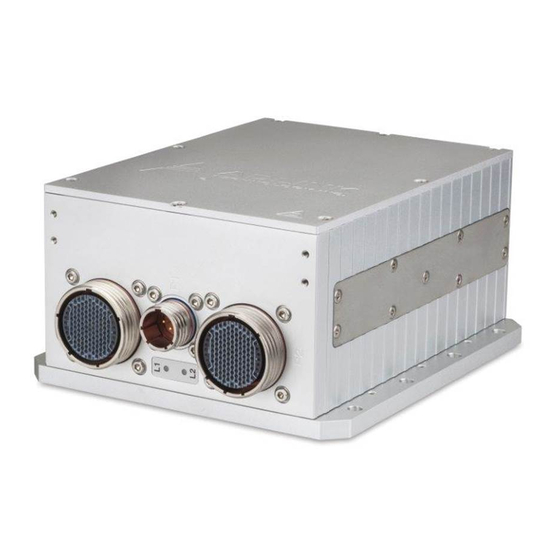
2.5 Front Panel Connectors & LEDs HPERC-KBL-MH P2 Military P3 Military P1 DC Connector Power In Connector HPERC-KBL-MC Figure 2-4: Front View of HPERC-KBL-M I/O Panel... -
Page 23: Table 2-1: I/O Panel Connectors
HPERC-KBL-M Connector & LED Descriptions Refer to Figure 2-4 for connector locations. Table 2-1: I/O Panel Connectors Connector Description P1: DC Power In This Military Power connector accepts DC voltages from an external source. Note: This connector is manufactured by Amphenol. This military connector provides signals for Ethernet Ports, USB P2: Military Connector 2.0, Serial Ports, Reset Switch, Ethernet LEDs, and UNDIO. -
Page 24: Breakout Cable Descriptions
2.6 Breakout Cable Descriptions RS-232/RS-422 Serial Ports Table 2-2: DB9 Male Connector Pin Definition Pin # RS232 RS422 — — GPIO Table 2-3: GPIO Breakout Wires Function/Label Signal GPIO1 P2-45 UDNIO13 GPIO2 P2-46 UDNIO14 GPIO3 P2-48 UDNIO15 GPIO4 P2-49 UDNIO16 GPIO5 P2-51 UDNIO17... -
Page 25: P2 And P3 Military Connectors
HPERC-KBL-M 2.7 P2 and P3 Military Connectors The following two tables define the signals and signal maps of the two military I/O connectors (P2 and P3) on the HPERC-KBL-M. Each table lists the P2 or P3 pin numbers, the signal names and descriptions. -
Page 26: P2 Pin Definitions
2.7.2 P2 Pin Definitions Table 2-4: P2 Connector Pin Definitions and Signal Maps P2 Pin Interface Signal Signal Description Gigabit Ethernet 1 GbE2_MDI0_P Ethernet10 MDI0 Positive Gigabit Ethernet 1 GbE2_MDI1_N Ethernet1 MDI1 Negative Gigabit Ethernet 1 GbE2_MDI1_P Ethernet1 MDI1 Positive Ground Ground Gigabit Ethernet 1... - Page 27 HPERC-KBL-M Table 2-4: P2 Connector Pin Definitions and Signal Maps P2 Pin Interface Signal Signal Description Control/Indicator HPOUT_L Audio Left Ground Ground Not Connected Not Connected Ground Ground Ground Ground User Defined IO UDNIO11 User Input/Output Port 11 User Defined IO UDNIO12 User Input/Output Port 12 Ground...
- Page 28 Table 2-4: P2 Connector Pin Definitions and Signal Maps P2 Pin Interface Signal Signal Description User Defined IO UDNIO4 User Input/Output Port 4 Ground Ground Not Connected Not Connected Ground Ground Power Switch PWERBTN_HDR Powers on the system USB 2.0, Port 9 USB_PWR9 USB 2.0 +5V Power USB 2.0, Port 9...
-
Page 29: P3 Pin Definitions
HPERC-KBL-M 2.7.3 P3 Pin Definitions Table 2-5: P3 Connector Pin Definitions and Signal Maps P3 Pin Interface Signal Signal Description VGA_VSYNC Vertical Sync Ground Ground Ground Ground VGA_DDC_SCL Display Data Channel - Serial Clock VGA_DDC_SDA Display Data Channel - Serial Data Ground Ground Red Analog Output... - Page 30 Table 2-5: P3 Connector Pin Definitions and Signal Maps P3 Pin Interface Signal Signal Description Gigabit Ethernet 2 GbE3_MDI2_N Ethernet2 Negative Gigabit Ethernet 2 GbE3_MDI2_P Ethernet2 Positive Ground Ground Gigabit Ethernet 2 GbE3_MDI3_N Ethernet3 Negative Gigabit Ethernet 2 GbE3_MDI3_P Ethernet3 Positive Ground Gigabit Ethernet 2 GbE3_MDI1_N...
- Page 31 HPERC-KBL-M Table 2-5: P3 Connector Pin Definitions and Signal Maps P3 Pin Interface Signal Signal Description Digital Display Interface Port C, DVI 2 DDIC_P2 TMDS Data 0 Positive Digital Display Interface Port C, DVI 2 DDIC_N2 TMDS Data 0 Negative Ground Ground Ground...
- Page 32 Table 2-5: P3 Connector Pin Definitions and Signal Maps P3 Pin Interface Signal Signal Description +5 Volts Power, DisplayPort D Power Auxiliary Select +5 Volts Power, High Definition Power Control Run +5 Volts Power, Power PCIe_ETH_2/5_LED2 Ground Ground Ground Ground Gigabit Ethernet 3 GbE4_MDI1_N Ethernet1 Negative...
-
Page 33: Powering Up The Hperc-Kbl-M
HPERC-KBL-M 2.8 Powering Up the HPERC-KBL-M Apply power to the HPERC-KBL-M Connect the AC Mating Cable to the AC Adapter (see Figure 1-2). Plug in the DC Cable Connector from the AC Adapter to the DC IN jack on the HPERC-KBL-M. -
Page 34: Internal Components
2.9 Internal Components The HPERC-KBL-M enclosure allows installation and removal of components including solid state drives (SSDs), SD memory card, PCI/104-Express expansion module, and Mini PCIe Card. Opening and resealing any of the openings on the HPERC-KBL-M enclosure may compro- mise the IP67 ingress rating performance of the system. -
Page 35: Bios Setup
HPERC-KBL-M 3 BIOS Setup This chapter provides information on how to read information from and configure the BIOS Setup utility of the HPERC-KBL-M. 3.1 Menu Structure This section presents the primary menus of the BIOS Setup Utility. Use the following table as a quick reference for the contents of the BIOS Setup Utility. -
Page 36: Main
3.2 Main The Main Menu provides read-only information about your system and also allows you to set the System Date and Time. Refer to the tables below for details of the submenus and settings. 3.2.1 BIOS Information Feature Options Description BIOS Vendor Info only Vendor... -
Page 37: Me Fw Version
HPERC-KBL-M 3.2.4 ME FW Version Feature Options Description ME FW Version Info only Version 3.2.5 ME Firmware SKU Feature Options Description ME Firmware SKU Info only 3.2.6 SPI Clock Frequency Feature Options Description DOFR Support Info only Supported Read Status Clock Info only Frequency Frequency... -
Page 38: System Management
3.2.8 System Management 3.2.8.1 Version Feature Options Description Version Info only Version 3.2.8.2 Board Information Feature Options Description SEMA Firmware Info only Display SEMA Firmware. Build Date Info only Display SEMA firmware build date. SEMA Boot loader Info only Display SEMA boot loader. Build Date Info only Display SEMA boot loader build date. - Page 39 HPERC-KBL-M Feature Options Description P_+3V3_A Read only Display actual voltage of the P_+3V3_A Read only Display actual voltage of the 3V3 VPTC Read only Display actual voltage of the VPTC Read only Display actual voltage of the 5V0 VIN(12V) Read only Display actual voltage of the VIN(12V) P_+5V_ATX Read only...
-
Page 40: System Language
3.2.9 System Language Feature Options Description System Language Choose the system default language English 3.2.10 System Date and Time Feature Options Description System Date Day, MM/DD/YYYY Set the date. Use Tab to switch between Date elements System Time HH/MM/SS Set the Time. Use Tab to switch between Time elements... -
Page 41: Advanced
HPERC-KBL-M 3.3 Advanced 3.3.1 CPU Configuration Feature Options Description CPU Signature Info only Display CPU Signature Processor Cores Info only Display number of processor cores CPU Speed Info only Display CPU frequency L1 Data Cache Info only Display L1 data cache size L1 Instruction Cache Info only Display L1 Instruction cache size... -
Page 42: Power & Performance
3.3.2 Power & Performance 3.3.2.1 CPU-Power Management Control Feature Options Description Intel(R) SpeedStep(TM) Enabled Allows more than two frequency ranges to be Disabled supported. Intel(R) Speed Shift Enable/Disable Intel(R) Speed Shift Enabled Technology Disabled Technology support. Enabling will expose the CPPC v2 interface to allow for hardware controlled P-states. -
Page 43: Pch-Fw Configuration
HPERC-KBL-M 3.3.3 PCH-FW Configuration Feature Options Description ME FW Version Info only ME Firmware Mode Info only ME Firmware Type Info only ME Firmware SKU Info only ME File System Integrity Info only Value ME Firmware Status 1 Info only ME Firmware Status 2 Info only NFC Support... -
Page 44: Nct6106D Super Io Configuration
Feature Options Description Device Select TPM 1.2 TPM 1.2 will restrict support to TPM 1.2 TPM 2.0 devices, TPM 2.0 will restrict support to TPM 2.0 devices, Auto will support both with the Auto default set to TPM 2.0 devices if not found, TPM 1.2 devices will be enumerated 3.3.5 NCT6106D Super IO Configuration... - Page 45 HPERC-KBL-M Feature Options Description Change Setting Select an optimal settings for Super IO device. Auto IO=2F8h;IRQ=3; IO=3F8h;IRQ=3,4,5,6,7,10, 11,12 IO=2F8h;IRQ=3,4,5,6,7,10, 11,12 IO=3E8h;IRQ=3,4,5,6,7,10, 11,12 IO=2E8h;IRQ=3,4,5,6,7,10, 11,12 RS232/RS422 RS232/RS422 selection RS232 RS422 3.3.5.3 NCT6106D Super IO > Serial Port 3 Configuration Feature Options Description Serial Port Disabled...
-
Page 46: Nct5104Dsec Super Io Configuration
Feature Options Description RS232/RS422 RS232/RS422 selection RS232 RS422 3.3.6 NCT5104DSEC Super IO Configuration Feature Options Description Super IO Chip Info only NCT5104DSEC Serial Port 1 Submenu Set Parameters of Serial Port 1 (COMA) Configuration Serial Port 2 Submenu Set Parameters of Serial Port 2 (COMB) Configuration Serial Port 3 Submenu... -
Page 47: Serial Port Console Redirection
HPERC-KBL-M 3.3.6.3 NCT5104DSEC Super IO > Serial Port 3 Configuration Feature Options Description Serial Port Disabled Enable or Disable Serial Port (COM) Enabled Device Settings Info only Change Setting Select an optimal settings for Super IO Auto IO=250h;IRQ=7; device. IO=240h;IRQ=3,4,5,7,10,11,12; IO=248h;IRQ=3,4,5,7,10,11,12;... - Page 48 Feature Options Description Console Redirection Submenu The settings specify how the host computer Settings and the remote computer (which the user is using) will exchange data. Both computers should have the same or compatible settings. COM5 Console Redirection Console Redirection Enable or Disable. Disabled Enabled Console Redirection...
- Page 49 HPERC-KBL-M Feature Options Description Bits per second 9600 Selects serial port transmission speed. The speed 19200 must be matched on the remote computer. Long or 38400 noisy lines may require lower speeds. 57600 115200 Data Bits Data Bits. Parity A parity bit can be sent with the data bits to detect None Even some transmission errors.
- Page 50 3.3.7.2 Serial Port Console Redirection > Legacy Console Redirection Settings Feature Options Description Redirection COM Port Select a COM port to display redirection of COM1 COM2 Legacy OS and Legacy OPROM Messages COM3 COM4 COM5 COM6 COM7 Legacy OS Redirection On legacy OS, the number of rows and 80x24 Resolution...
-
Page 51: Network Stack Configuration
HPERC-KBL-M 3.3.8 Network Stack Configuration Feature Options Description Network Stack Enable/Disable UEFI network stack. Disabled Enabled Ipv4 PXE Support Enable/Disable Ipv4 PXE Boot Support. If Disabled Enabled disabled, IPV4 PXE boot support will not be available. Ipv4 HTTP Support Enable/Disable IPv4 HTTP boot support. If Disabled Enabled disabled, IPv4 HTTP boot support will not be... -
Page 52: Usb Configuration
Feature Options Description Video Do not launch Controls the execution of UEFI and Legacy UEFI Video OpROM Legacy Other PCI device Do not launch Determines OpROM execution policy for UEFI devices other than Network, Storage, or Video Legacy 3.3.10 USB Configuration Feature Options Description... -
Page 53: Chipset
HPERC-KBL-M 3.4 Chipset 3.4.1 System Agent (SA) Configuration Feature Options Description System Agent Bridge Info only Name SA PCIe Code Version Info only VT-d Disabled VT-d capability Enable Memory Configuration Submenu Memory Configuration Parameters PEG Port Configuration Submenu PEG Port Options 3.4.1.1 System Agent Configuration >... -
Page 54: Pch-Io Configuration
3.4.2 PCH-IO Configuration Feature Options Description PCI Express Submenu PCI Express Configuration Settings Configuration SATA and RST Submenu SATA Device Options Settings Configuration HD Audio Configuration Submenu HD Audio Subsystem Configuration settings 3.4.2.1 PCH-IO Configuration > PCI Express Configuration Feature Options Description PCI Express Root Port 1... - Page 55 HPERC-KBL-M Feature Options Description Port 0 Disabled Enable/Disable SATA Port. Enabled Hot Plug Designates this port as Hot Pluggable. Disabled Enabled Serial ATA Port 1 Software Preserve Port 0 Disabled Enable/Disable SATA Port. Enabled Hot Plug Designates this port as Hot Pluggable. Disabled Enabled Serial ATA Port 2...
- Page 56 3.4.2.4 PCH-IO Configuration > HD Audio Configuration Feature Options Description HD Audio Disabled Control Detection of the HD Audio device. Disabled = HD Audio will be unconditionally Enable Auto disabled Enabled = HD Audio will be unconditionally Enabled Auto = HD Audio will be enabled if present, disabled otherwise.
-
Page 57: Security
HPERC-KBL-M 3.5 Security 3.5.1 Password Description If ONLY the Administrator’s password is set, then this only limits access to Setup and is only asked for when entering Setup. If ONLY the User’s password is set, then this is a power on password and must be entered to boot or enter Setup. -
Page 58: Boot
3.6 Boot 3.6.1 Boot Configuration Feature Options Description Setup Prompt Timeout Number of seconds to wait for setup activation key. 65535 (0xFFFF ) means indefinite waiting. Bootup NumLock State Select the keyboard NumLock state. Quiet Boot Disabled Enable or disables Quiet Boot option Enabled Boot Option Priorities Boot Option #1... -
Page 59: Save & Exit
HPERC-KBL-M 3.7 Save & Exit Feature Options Description Save Changes and Exit Yes Exit system setup after saving the changes. Discard Changes and Exit system setup without saving any Exit changes. Save Changes and Reset the system after saving the changes. Reset Discard Changes and Reset system setup without saving any... - Page 60 This page intentionally left blank.
-
Page 61: Important Safety Instructions
HPERC-KBL-M Important Safety Instructions For user safety, please read and follow all instructions, WARNINGS, CAUTIONS, and NOTES marked in this manual and on the associated equipment before handling/operating the equipment. Read these safety instructions carefully. Keep this user’s manual for future reference. Read the specifications section of this manual for detailed information on the operating environment of this equipment. - Page 62 This page intentionally left blank. Important Safety Instructions...
-
Page 63: Getting Service
6450 Via Del Oro, San Jose, CA 95119-1208, USA Tel:+1-408-360-0200 Toll Free:+1-800-966-5200 (USA only) Fax:+1-408-600-1189 Email: info@adlinktech.com ADLINK Technology (China) Co., Ltd. 300 Fang Chun Rd., Zhangjiang Hi-Tech Park, Pudong New Area, Shanghai, 201203, China Tel: +86-21-5132-8988 Fax: +86-21-5132-3588 Email: market@adlinktech.com ADLINK Technology GmbH Hans-Thoma-Straße 11, D-68163 Mannheim, Germany...
Need help?
Do you have a question about the HPERC-KBL-MC and is the answer not in the manual?
Questions and answers