
Related Manuals for ADLINK Technology MCM-216


Summary of Contents for ADLINK Technology MCM-216
- Page 1 MCM-216/218 Standalone Ethernet DAQ for Distributed Machine Condition Monitoring User’s Manual Manual Rev.: May 10, 2021 Revision Date: 50M-00024-1000 Part No:...
- Page 2 Revision History Revision Release Date Description of Change(s) 2021-05-10 Initial Release...
- Page 3 MCM-216/218 Preface Copyright © 2021 ADLINK Technology Inc. This document contains proprietary information protected by copy- right. All rights are reserved. No part of this manual may be repro- duced by any mechanical, electronic, or other means in any form without prior written permission of the manufacturer.
- Page 4 California Proposition 65 Warning WARNING: This product can expose you to chemicals including acrylamide, arsenic, benzene, cadmium, Tris(1,3-dichloro-2-propyl)phosphate (TDCPP), 1,4-Diox- ane, formaldehyde, lead, DEHP, styrene, DINP, BBP, PVC, and vinyl materials, which are known to the State of California to cause cancer, and acrylamide, benzene, cadmium, lead, mercury, phthalates, toluene, DEHP, DIDP, DnHP, DBP, BBP, PVC, and vinyl materials, which are known to the State of California to cause...
-
Page 5: Table Of Contents
Reset Pin for Factory Default ........16 1.5.5 Ethernet Ports............17 1.5.6 LED Indicators ............17 1.5.7 USB Ports..............17 2 Getting Started ..............19 Unpacking the MCM-216/218 ..........19 Connecting to I/O............... 19 Connecting/Disconnecting Power........20 Table of Contents... - Page 6 Checking Device Status............. 20 Usage Scenarios..............20 2.5.1 First-Time Configuration / Portable DAQ ....21 2.5.2 Periodic Polling (REST API) ........21 2.5.3 TCP Socket for Streaming ........21 2.5.4 Passive Data (TCP Socket) ........21 3 Web Console ..............23 Web Console Login............
-
Page 7: List Of Figures
MCM-216/218 List of Figures Figure 1-1: Front View ..............7 Figure 1-2: Top View..............8 Figure 1-3: Left Side View............. 9 Figure 1-4: Right Side View ............10 Figure 1-5: DIN Rail Mount Dimensions ........11 Figure 1-6: Wall Mount Dimensions..........12 Figure 1-7: Wall Mount Assembly .......... - Page 8 Figure 3-30: Apply a New Mission ..........51 Figure 4-1: Operational Modes ........... 54 Figure 4-2: RESTful API.............. 55 viii List of Figures...
-
Page 9: Introduction
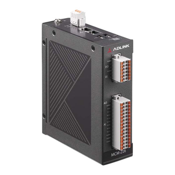
The MCM-216/218 is designed for on-site process automation in the field. When recovering from a power failure, the system will automatically resume previous running state. MCM-216/218's compact size also makes it easy to install in the limited confines of an electrical control cabinet. Introduction... -
Page 10: Features
1.1 Features Standalone Ethernet DAQ for edge computing RESTful API reports machine conditions to IT system TCP socket client mode for continuous data acquisition Built-in web console for easy configuration and to facilitate use as a portable DAQ Supports Modbus TCP server mode to upload data to SCADA system Supports custom filtering algorithms for edge data 8- or 16-channel, 16-bit analog input up to 250 kS/s... -
Page 11: Specifications
-50°C to 150°C (with 3 meter cable) Sensor (TI LMT01) 1.3.2 Analog Input Analog Input Specifications Number of Channels 8 for MCM-218, 16 for MCM-216 Resolution 16-bit Maximum Sampling 250 kS/s and can be shared by selected channels. Rate 100 KHz for multi-channel gain queue Input Range (voltage) ±10V, ±2.5V, ±1.25V, ±312.5mV... -
Page 12: Isolated Digital I/O
±0.1dB (20 Hz to 30 KHz) Trigger Sources Software, digital trigger, analog trigger, built-in button Overvoltage Protection ±15 V Input Impedance MCM-216: >1G ohm MCM-218: ±249 ohms CMRR 105 dB for ±1.25 V & ±0.3125 V 95 dB for ±2.5 V 85 dB for ±10 V... -
Page 13: Analog Ouptut Specifications
MCM-216/218 1.3.4 Analog Ouptut Specifications Analog Ouptut Specifications Resolution 16-bit Number of Channels 2 channels for voltage and current Maximum Update Rate 100 Ksps and settling time 10 μs Output Range AO Current output: Maximum Load: 600 ohm AO Voltage Output Range: ±10 V... -
Page 14: Environmental
1.3.6 Environmental Environmental Specifications Operating Temperature 0°C to 70°C (32°F to 158°F) Storage Temperature -20°C to 85°C (-4°F to 185°F) Humidity Approx. 95% @ 40°C (non-condensing) Vibration Operating: 5 Grms, 5-500 Hz, 3 axes Shock Operating: 100 G, half sine 11 ms duration EN61000-6-4/EN61000-6-2 FCC Part 15B Class A, CISPR 32 IEC 61000-4-2 ESD: Contact: 4 kV;... -
Page 15: Mechanical Drawings
MCM-216/218 1.4 Mechanical Drawings 1.4.1 Dimensions Units: mm Figure 1-1: Front View Introduction... -
Page 16: Figure 1-2: Top View
Units: mm Figure 1-2: Top View Introduction... -
Page 17: Figure 1-3: Left Side View
MCM-216/218 111.65 Units: mm Figure 1-3: Left Side View Introduction... -
Page 18: Figure 1-4: Right Side View
111.65 Units: mm Figure 1-4: Right Side View Introduction... -
Page 19: Din Rail Mount
MCM-216/218 1.4.2 DIN Rail Mount The DIN rail mount may be attached to the MCM-216/218 using two flat head screws (included). Units: mm 89.18 80.43 78.38 70.75 41.1 Figure 1-5: DIN Rail Mount Dimensions Introduction... -
Page 20: Wall Mount
1.4.3 Wall Mount The optional wall mount bracket may be attached to the MCM-216/218 via four pan head screws (included with wall mount kit, P/N 34-51112-0000; see Figure 1-7 on page 13). 80.0 Units: mm 61.6 20.0 70 100 106 Ø... -
Page 21: Figure 1-7: Wall Mount Assembly
MCM-216/218 Figure 1-7: Wall Mount Assembly Introduction... -
Page 22: I/O Connectors
4 LED indicator lights 1.5.1 Analog Input and Analog Output The MCM-216/218 module is equipped with a 2x14-pin terminal block for analog output and analog input. There are 2 analog out- put channels and 16 channels for analog input. The A.GND pin is for grounding. -
Page 23: Digital Input And Output
Figure 1-9: Digital Input/Output Connector 1.5.3 Temperature Sensor Input The MCM-216/218 allows you to monitor the temperature of a tar- get device or environment between -50 to 150°C using the tem- perature sensor provided. Connect the temperature sensor leads to the connector as shown. -
Page 24: Reset Pin For Factory Default
1.5.4 Reset Pin for Factory Default Restore the MCM-216/218 to its factory default settings using a paper clip or similar item inserted into the reset pin hole button and pressing the reset button for three seconds until the device reboots. -
Page 25: Ethernet Ports
MCM-216/218 1.5.5 Ethernet Ports The MCM-216/218 has two GbE ports with one MAC address. Either port can be used for connecting to a host PC, leaving the second port available for cascading. The default static IP address is 169.254.1.1. LED1 (Amber) LED2 (Green) Link/Activity... - Page 26 This page intentionally left blank. Introduction...
-
Page 27: Getting Started
Ethernet port to cascade them together. Cascad- ing reduces the number of ports needed to connect devices. If connecting MCM-216/218 devices in a daisy chain, only use a sequence configuration: do not use a ring configuration. A ring configuration will cause network communications to fail. -
Page 28: Connecting/Disconnecting Power
PWR LED will light up. If the needs to be shut down, turn off the power MCM-216/218 source. To remove the power wires, use a flat head screwdriver to push the orange slots on the terminal block and then pull out the wires. -
Page 29: First-Time Configuration / Portable Daq
MCM-216/218 2.5.1 First-Time Configuration / Portable DAQ Use the web console to configure device information, system set- tings, network settings, and test measurement analog input set- tings. For portable DAQ usage, the has a built-in MCM-216/218 dashboard to show the results of acquired data. The web-based console is also a convenient tool for users unfamiliar with DAQ behavior or programming. - Page 30 This page intentionally left blank. Getting Started...
-
Page 31: Web Console
MCM-216/218 Web Console This chapter describes how to use the built-in web console to configure the and view captured data. MCM-216/218 3.1 Web Console Login After the has been successfully powered on and a MCM-216/218 host PC has been connected to it, do one of the following: (1) set the PC’s network setting to either DHCP mode or link local mode;... -
Page 32: Figure 3-1: Web Console Login Page
Figure 3-1: Web Console Login Page Web Console... -
Page 33: Web Console Menu
MCM-216/218 3.2 Web Console Menu The web console menu bar includes the following items. Mission Manager Device Setting Mission Management Peripheral Data Manager Data Capture Data History Data Condition TCP Socket USB Storage Modbus TCP Server Modbus RTU Mater Information... -
Page 34: Figure 3-2: Web Console Welcome Page
Figure 3-2: Web Console Welcome Page Depending on the host PC screen size and resolution, the menu list might be collapsed. Click the menu icon to expand the menu. Figure 3-3: Menu Icon Web Console... -
Page 35: Information/System Information
MCM-216/218 3.2.1 Information/System Information The System Information page shows the device software version, general information, I/O channel status, and network status. Figure 3-4: System Information Web Console... -
Page 36: Mission Manager/Peripheral
3.2.2 Mission Manager/Peripheral Peripheral digital input/output and temperature sensor information is shown on this page. The Status area shows the current status of the peripherals. Select REFRESH to update the status. Four digital input/output devices can be used. Each can be adjusted for either input or output mode. -
Page 37: Data Manager/Data History
The MCM-216/218 will execute the same settings even after a reboot, so if Repeat Times is set to 0 (endless data cap- ture), the MCM-216/218 will run its previous mission after reboot. To configure the I/O parameters for another mission, delete the current mission. -
Page 38: System Manager/Change Password
3.2.5 System Manager/Change Password This page is used to change the password of each MCM-216/218, whether there is a single device or multiple daisy chained devices. It is recommended that each device have a unique password since the default password for every MCM-216/218 is identical. -
Page 39: System Manager/Network Setting
MCM-216/218 3.2.7 System Manager/Network Setting This page manages various system settings. Hostname: The device’s hostname can be modified by entering a new hostname here and clicking the APPLY button. A hostname can be used instead of an IP address to access a specific device’s web console. -
Page 40: System Manager/System Setting
RESTART to soft reboot the device. Data Keep: By default, the MCM-216/218 stores history data only in RAM and the data is lost when the system reboots. Select Enable to also save history data to internal storage. The amount of disk space allocated for this purpose is 300MB. -
Page 41: Figure 3-12: Upload Customization/Firmware Files
See “Custom Fil- MCM-216/218 tering Algorithms” on page 56. Firmware Upgrade: A firmware upgrade file can be uploaded to the MCM-216/218 through this feature. These files will periodically be provided through the product web page: www.adlinktech.com/Products/IoT_solutions/Smart_Factory/ MCM-210_Series... -
Page 42: Data Manger/Tcp Socket (For One-Shut Query Mode)34
TCP socket server. If the socket is disconnected, select RE-CONNECT ALL to re-establish the connection. Figure 3-13: TCP Socket After setting the TCP socket connection and creating a DAQ mis- sion, data generated by the MCM-216/218 will immediately begin transmitting to the TCP server side. Web Console... -
Page 43: Device Manager/Modbus Tcp Server
In addition to the REST API, the Modbus TCP protocol can be used to access data generated from the MCM-216/218. The MCM-216/218 acts as a Modbus TCP server, and a remote Mod- bus TCP client can actively query the MCM-216/218. -
Page 44: Figure 3-15: Data Types For Modbus Tcp
The following examples show channels AI0 with two data types, AI1 with one data type, and AI2 with one data type. Figure 3-15: Data Types for Modbus TCP Web Console... -
Page 45: Figure 3-16: Modbus Tcp Created Data Types
MCM-216/218 In the Modbus TCP settings page, the data value column will show the created data types. Each data type in an analog input channel occupies 2 modbus registers read by modbus function code 4, starting from address 30001. Figure 3-16: Modbus TCP Created Data Types... -
Page 46: Figure 3-17: Data Value Starting Address Allocation
Now, you can allocate the register sequence accordingly. Figure 3-17: Data Value Starting Address Allocation Web Console... -
Page 47: Figure 3-18: Modbus Function Codes
MCM-216/218 Other peripherals, such as digital input, digital output, and analog output can be operated by different Modbus function codes and addresses. Figure 3-18: Modbus Function Codes Web Console... -
Page 48: Daq Mission
3.3 DAQ Mission The MCM-216/218 performs signal detection. Related parameters can be set via the Mission Manger/Device Setting page. Figure 3-19: Device Configuration Web Console... -
Page 49: Figure 3-20: Post Trigger Without Retrigger
MCM-216/218 AI Data Mode: There are two kinds of data query modes. One Shut Mode queries data by time interval. By configuring all the settings, including repeat interval, repeat times, and sample rate, the device will query data accordingly. Streaming Mode, with a TCP socket, queries data continu- ously. -
Page 50: Figure 3-21: Pre-Trigger Mode Operation (Valid Trigger Only)
event by a specified amount, as shown. Note that N must be equal to or less than 8k samples for all analog input channels. Trigger Event Occurs Acquisition stop Operation start Begin to transfer data to Acquisition start system Time Trigger Data N samples... -
Page 51: Figure 3-23: Delay-Trigger Mode Operation
MCM-216/218 Delay-Trigger Acquisition (no retrigger) Delays data collection after the trigger event, as shown. The delay count is specified by a 32-bit counter value, such that the maxi- mum delay count is (2 -1) when the minimum delay count is 1. -
Page 52: Figure 3-25: Gated Trigger
Gated Trigger Gated-trigger acquisition is indicated in applications where data is to be collected when trigger events are set to level high/low, and acquisition suspended when trigger events are set to the opposite level. The process repeats until the specified amount of data is acquired. - Page 53 (+/-) adjust- ments. The MCM-216/218 provides the Channel Gain Queue function to dynamically allocate sampling size. By default, the selected chan- nels will equally share the maximized sample rate. However, sam- pling rates can be allocated as necessary between channels.
-
Page 54: Figure 3-26: Datatype
can manually set the sample rate according to the device each channel connects to. For each analog input channel, click DataType to choose which data type to use for the output. Figure 3-26: DataType An input range can be selected, as below. Web Console... - Page 55 MCM-216/218 Depending on the channels selected, the Channel Config proper- ties of each channel will be shown. has built-in functionality for several common MCM-216/218 data types and also supports user-customized data types, as detailed in the table below. If two or more data types are required for an analog input channel, select ADD DATATYPE for each additional data type.
-
Page 56: Figure 3-27: Add Condition
ADD CONDITION provides an event warning mechanism. When a given condition is triggered, a warning message will display on the Data Condition page. Figure 3-27: Add Condition After the desired settings have been configured, click APPLY to activate your changes. Analog Output Web Console... - Page 57 MCM-216/218 The MCM-216/218 has two analog output channels: output volt- age, or current with a predefined value. Web Console...
-
Page 58: Figure 3-28: Data Capture
The Data Manager/Data Capture page displays DAQ results in real time. You can use the data capture function in lab testing or as a portable DAQ device. Raw data and Voltage can be converted to charts for troubleshooting. Figure 3-28: Data Capture Figure 3-29: Device Settings Web Console... - Page 59 MCM-216/218 Settings may be saved as a Mission Profile (JSON file) for backup or for convenient duplication on other devices. Click MCM-216/218 SAVE PROFILE to download the file to your PC. To import a Mis- sion Profile to an device, click Choose File under MCM-216/218 Select Mission Profile and select the desired configuration file.
- Page 60 This page intentionally left blank. Web Console...
-
Page 61: Daq Missions
For the periodic polling mode, MCM-216/218 provides a REST API and sample code in C#, Python, and JavaScript. Alternatively, for continuous data mode, MCM-216/218 provides a Streaming SDK and associated C/C++ sample code. -
Page 62: Web Console
4.1.1 Web Console The MCM-216/218 has a built-in, easy-to-use web console that implements all device functionalities. By logging into the web con- sole through a connected host PC, users can see all of the device’s current settings, each feature it provides, and any vibra- tion data it has collected. -
Page 63: Periodic Polling
MCM-216/218 serving as responder. After receiving a query from the host, the MCM-216/218 responds with the requested data. However, for some applications it’s desir- able for the host server to passively wait for data from the client. In... -
Page 64: Custom Filtering Algorithms
4.2 Custom Filtering Algorithms The MCM-216/218 offers flexible support options for custom filter- ing algorithms. Users can easily import their own domain-knowl- edge algorithms to the MCM-216/218. Custom filtering algorithms must be written in C or C++ and compiled under Linux. - Page 65 MCM-216/218 5. Upload customAlgo.so to the MCM-216/218 from the web console System Setting page. 6. After it uploads, log back into the web console. DAQ Missions...
- Page 66 7. After logging in, choose Customization as the data type, set parameters as needed, then click APPLY to apply the task to the MCM-216/218. 8. Check the results on the data capture page. DAQ Missions...
-
Page 67: Important Safety Instructions
MCM-216/218 Important Safety Instructions For user safety, please read and follow all instructions, Warnings, Cautions, and Notes marked in this manual and on the associated device before handling/operating the device, to avoid injury or damage. S'il vous plaît prêter attention stricte à tous les avertissements et mises en garde figurant sur l'appareil , pour éviter des blessures... - Page 68 A Lithium-type battery may be provided for uninterrupted backup or emergency power. Risk of explosion if battery is replaced with one of an incorrect type; please dispose of used batteries appropriately. Risque d’explosion si la pile est remplacée par une autre de CAUTION: type incorrect.
-
Page 69: Getting Service
San Jose, CA 95138, USA Tel: +1-408-360-0200 Toll Free: +1-800-966-5200 (USA only) Fax: +1-408-360-0222 Email: info@adlinktech.com ADLINK Technology (China) Co., Ltd. 300 Fang Chun Rd., Zhangjiang Hi-Tech Park Pudong New Area, Shanghai, 201203 China Tel: +86-21-5132-8988 Fax: +86-21-5132-3588 Email: market@adlinktech.com ADLINK Technology GmbH Hans-Thoma-Straße 11...
Need help?
Do you have a question about the MCM-216 and is the answer not in the manual?
Questions and answers