Table of Contents
Advertisement
Quick Links
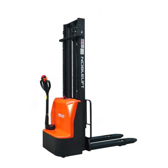
INSTRUCTION MANUAL
Electric Stacker PSE15L-C2
WARNING
Do not use the electric truck before reading and
understanding these operating instructions.
NOTE:
●
Please check the designation of your present type
at the last page of this document as well as on the
ID-plate.
●
Keep for future reference.
This truck should be used in factories,
tourist attractions and playgrounds only.
1
Version 08/2023
PSE15L-C2-SMS-001-EN
Advertisement
Table of Contents

Related Manuals for Noblelift PSE15L-C2


Summary of Contents for Noblelift PSE15L-C2
- Page 1 INSTRUCTION MANUAL Electric Stacker PSE15L-C2 WARNING Do not use the electric truck before reading and understanding these operating instructions. NOTE: ● Please check the designation of your present type at the last page of this document as well as on the ID-plate.
- Page 2 FOREWORD Before operating the stacker, read this ORIGINAL INSTRUCTION MANUAL carefully and understand the usage of the stacker completely. Improper operation could create danger. This manual describes the usage of different electric power stackers. When operating and servicing the stacker, make sure, that it applies to your type. Keep this manual for future reference.
-
Page 3: Table Of Contents
Table of Contents 1.CORRECT APPLICATION ............................3 2.DESCRIPTION OF THE ELECTRIC STACKER ....................4 a.Overview of the main parts............................4 b.Main technical data ..............................5 c. Description of safety devices and warning labels (Europe and others, except USA) ..........7 d.Frame number position ............................ -
Page 4: Correct Application
1.CORRECT APPLICATION It is only allowed to use this electric pallet stacker according to this instruction manual. The stackers described in this manual are self-propelled electric power pallet stackers. The stackers are designed to lift, lower and transport palletized loads. A wrong usage can cause human injuries or can damage the stacker. -
Page 5: Description Of The Electric Stacker
2.DESCRIPTION OF THE ELECTRIC STACKER a.Overview of the main parts Fig. 1: Overview main parts Motor cover Emergency button Body protective cover Drive wheel Emergency stop panel cover Steering wheel External charger interface Truck body Belly button Fork Load wheel Accelerator knob (butterfly knob) Multi-function tiller Hydraulic system... -
Page 6: B.main Technical Data
Fig. 2: Technical data Table1: Main technical data for standard version Type sheet for industrial truck according to VDI 2198 PSE15L-C2 Manufacturer’s type designation 1600 3600 Drive: electric (battery type, mains...), diesel, petrol, fuel Electric Pedestrian Operator type (hand, pedestrian, standing, order picker) - Page 7 (mm) 1980 4039 Height, mast extended 670/1228 Height drawbar in driving position min./max. 4.15 Height, lowered 1805 4.19 Overall length (mm) 4.20 Length to face of forks (mm) 4.21 (mm) Overall width 60/180/1150 4.22 s/ e/ l(mm) Fork dimensions DIN ISO 2331 570/685 4.25 Fork spread...
-
Page 8: Description Of Safety Devices And Warning Labels (Europe And Others, Except Usa)
c. Description of safety devices and warning labels (Europe and others, except USA) Decal (crane hook) Warning decal (do not stand under or on the forks) Label (load curve) Decal (read and follow these instructions) Decal (no passenger) Label (ID plate) Label (oil filling) The truck equips with an emergency button (9) which stops all lifting-, lowering-, driving- functions and engages the fail-safe electromagnetic... -
Page 9: E.identification Plate
e.Identification plate Fig.5:ID-plate location The Identification plate is located on the left or right side of the vehicle body. position Electric Stacker Special Equipment Manufacturing License No. Type xxxx Rated capacity xxxx Rated voltage Service weight xxxx Battery weight, Battery weight, minimum maximum Weight, without load... -
Page 10: Warnings, Residual Risk And Safety Instructions
3. WARNINGS, RESIDUAL RISK AND SAFETY INSTRUCTIONS DO NOT • Lift the load higher than the lift point when operating the stacker outdoors. • Put feet or hands under or inside the lifting mechanical structure. • Allow other person than the operator to stand in front of or behind the stacker when it is moving or lifting/ lowering. -
Page 11: Commissioning, Transporting, Decommissioning
4.COMMISSIONING, TRANSPORTING, DECOMMISSIONING a.Commissioning Table 2: Commissioning data Type PSE15L-C/1600 PSE15L-C/3600 Commissioning weight [kg] Dimensions [mm] 1600 3600 After receiving our new pallet stacker or for re-commissioning you have to do following before (firstly) operating the truck: • Check if are all parts included and not damaged •... -
Page 12: C.storage / Decommissioning
Hoisting Use dedicated crane and hoisting equipment. Do not stand under the swaying load. Do not walk into hazardous area during hoisting. Park the truck securely and lash the truck according to the points identified in Fig. 6. Hoist the truck to its destination and place the truck securely before removing the hoisting equipment. -
Page 13: Daily Inspection
5.DAILY INSPECTION This chapter describes pre-shift checks before putting the truck into operation. Daily inspection is effective to find the malfunction or fault on this truck. Check the truck on the following points before operation. Remove load from truck and lower the forks. REMOVE LOAD FROM TRUCK AND LOWER THE FORKS. -
Page 14: A.parking
Ensure that the goods are placed horizontally and stably, and conduct daily inspections. At the beginning, insert the magnetic key. Magnetic keys can only be used on walking controlled electric stackers. Before finally placing the magnetic key, the emergency stop button must be carefully pulled out. Press horn button 21 (Figure 9) to activate the horn. -
Page 15: D.lowering
d.Lowering If the forks are in the racking, firstly travel out of the racking carefully with or without the pallet. By travelling out of the racking, take care that the forks are not touching the racking. Press the lowering button (Fig. 9, 23) carefully. Lower the load until the forks are clear of the pallet, then drive the truck carefully out of the load unit. -
Page 16: H.malfunctions
THE BRAKING PERFORMANCE DEPENDS ON THE TRACK CONDITIONS AND THE LOAD CONDITIONS OF THE TRUCK The braking function can be activated on several ways: • By moving the accelerator button (Fig.9, 13) back to the initial ‘0’ position or by releasing the button, the regenerative braking is activated. -
Page 17: A.replacement
• Park the truck securely before starting charging or installing/changing the batteries • Before finishing the maintenance work, make sure, that all cables are connected correctly and that there are no disturbing towards other components of the truck. For lead-acid models, this vehicle is equipped with the following sealed acid batteries: •... -
Page 18: B.battery Indicator
b.Battery Indicator The battery level display is divided into four compartments, each representing 25% of the battery level. The last 15% red light will flash, and at this point, the speed limit mode will enter. The output throttle of the handle is 50% of the full throttle, indicating the need for charging. c.Charging •... -
Page 19: A.maintenance Checklist
compression. Carelessness causes injury. • Use approved and from your dealer released original spare parts. • Please consider that oil leakage of hydraulic fluid can cause failures and accidents. • If you need to replace the wheel, please follow the instructions above. Casters must be round and free from abnormal wear. -
Page 20: B.lubricating Points
• 28 Check the battery voltage • 29 Clean and grease the terminals and check for corrosion and damage • 30 Check the battery housing for damages Charger • 31 Check the main power cable for damages • 32 Check the fail-safe protection during charging Function •... -
Page 21: C.check And Refill Hydraulic Oil
c.Check and refill hydraulic oil It is recommended to use hydraulic oil in connection with average temperature: Environment –5℃~25℃ >25℃ temperature HVLP 32, HLP 46, Type DIN 51524 DIN 51524 Viscosity 28.8-35.2 41.4 - 47 Amount 4L (depends on specific model) Waste material like oil, used batteries or other must be probably disposed and recycled according to the national regulations and if necessary brought to a recycling company. -
Page 22: E.removing, Reattaching Guarding
e.Removing, reattaching guarding DO NOT USE THIS TRUCK IF THE PROTECTIVE MESH IS DAMAGED OR NOT ASSEMBLED CORRECTLY! If you want to remove the protective mesh, remove the fixed screws and carefully remove the protective mesh. The screws are still on the truck. When you reassemble the protective mesh, place the mesh and fix each screw correctly. - Page 23 suddenly The electromagnetic brake is engaged. Repair or replace the accelerator. The relating tiller cables are Lift only the max. capacity, disconnected or damaged mentioned on the ID-plate The controller is damaged. Charge the battery Load can’t be lifted The accelerator not moves back to its Check and eventually replace the neutral position.
-
Page 24: Wiring/ Circuit Diagram
10.WIRING/ CIRCUIT DIAGRAM a.Electrical circuit diagram Fig. 18: Electrical diagram... - Page 25 Table 7: Description of electrical components Code Item Code Item 24V lead-acid battery Horn button Emergency switch accelerator Pump motor Belly button Pump contactor LED fault light Traction controller Brake 200A fuse Traction motor FU01 10A fuse charger key switch Horn Interlocking proximity switch Descent button...
-
Page 26: B.hydraulic Circuit Diagram
b.Hydraulic circuit diagram Fig. 19: Hydraulic circuit diagram Table 9: Description of hydraulic components Code Item Code Item Hydraulic power unit Throttle valve (motor and pump) One-way valve Cylinder Electromagnetic valve Safety valve Relief valve... -
Page 27: C.schematic Diagram Of Braking System
c.Schematic diagram of braking system...
Need help?
Do you have a question about the PSE15L-C2 and is the answer not in the manual?
Questions and answers