Table of Contents
Advertisement
Quick Links
INSTRUCTION HANDBOOK
Electric Stacker
WARNING
Do not use the electric truck beforereading
and understanding these
operatinginstructions.
NOTE:
Please check the designation of your
present type at the last page of this
document as well as on the ID-plate.
Keep for future reference.
Version 03/2017
PS 30RP-SMS-001-US
0
Advertisement
Table of Contents

Related Manuals for Noblelift PS 30RP


Summary of Contents for Noblelift PS 30RP
- Page 1 Do not use the electric truck beforereading and understanding these operatinginstructions. NOTE: Please check the designation of your present type at the last page of this Version 03/2017 document as well as on the ID-plate. PS 30RP-SMS-001-US Keep for future reference.
- Page 3 FOREWORD The content in this chapter is specialized for the US-American market. Operating this truck requires knowledge which can be acquired from this instruction handbook. This handbook must be kept available throughout the entire period of use of the industrial truck. IT IS LAW;...
-
Page 4: Table Of Contents
TABLE OF CONTENTS CORRECT APPLICATION ........................ 4 DESCRIPTION OF THE STACKER ....................5 Overview of the main components ....................5 Main technical data ........................6 Description of the safety devices and warning labels (US- market) ..........7 Identification plate ........................10 WARNINGS, RESIDUAL RISK AND SAFETY INSTRUCTIONS ............ -
Page 5: Correct Application
1. CORRECT APPLICATION It is only allowed to use this electric stacker according to this instruction handbook. The trucks described in this handbook are self propelledpedestrian controlledelectric power stacker,with electrically powered lifting function. The trucks are designed for stacking operations in dedicated racking by lifting and lowering the palletized load up to the desired lifting height. -
Page 6: Description Of The Stacker
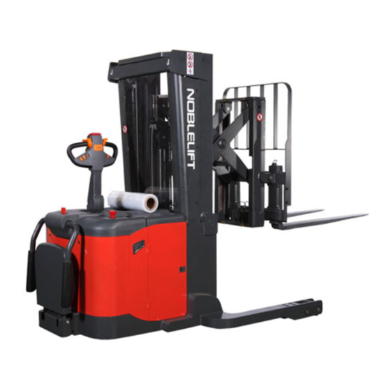
2. DESCRIPTION OF THE STACKER Overview of the main components Fig. 1: Overview main components (butterfly- button) Forks 12. Accelerator Load wheels 13. Battery cover Door 14. Reach Pantograph Key switch 15. Mast Discharge indicator and charging indicating 16. Protective board 17. -
Page 7: Main Technical Data
Main technical data Fig. 2: Technical data Table1: Main technical data for standard version(US market) Technical data sheet for industrial truck acc. to VDI 2198 PS 30RP Manufacturer`s type designation Power (battery ,diesel,petrol Battery gas,manual) Operator type Pedestrian Load Capacity / rated load Q(lbs) 3086.5... -
Page 8: Description Of The Safety Devices And Warning Labels (Us- Market)
Tread, rear b11 (in) 38.2-54.2 Tilt of mast/fork carriage ° forward/backward Lowered mast height h1 (in) Free Lift height h2 (in) Lift h3 (in) Extended mast height h4 (in) Height of tiller in drive position min./ h14 (in) 47.2/55.9 max. 4.15 Height, lowered h13 (in) - Page 9 K. Sign warning stay clear stop truck L. Sign danger not riding M. Sign warning electrical devices N. Sign danger being crushed The truck has an emergency button(6) which stops all lifting-, lowering-, driving- functions and engages the failsafe electromagnetic brake when it is pushed.By pulling this button, the truck can be operated after the controller checked the functions.
- Page 10 Sign read and follow this instruction (F) Sign not under, on forks(H) Sign danger not riding (L) (only if not equipped with a foldable plat Sign danger battery (I) Sign warning electrical devices (M) Sign danger being crushe d (N) Sign oil filling point (J) Sign warning stay clear stop truck (K)
-
Page 11: Identification Plate
Identification plate Designation, type Name and address of manufacturer) Serial number Hour rate Rated capacity in lbs 10 Battery weight minimum/ maximum Supply voltage in V 11 Nominal power in kW Own mass (self weight) in kg without 12 Load center distance battery 13 Manufacturing date Max. -
Page 12: Commissioning, Transporting,Decommissioning
To prevent unintended sudden movements when not operating the truck (i.e. from another person, etc.) switch off thetruck and remove the key. 4. COMMISSIONING, TRANSPORTING,DECOMMISSIONING Commissioning Table 2: Commissioning data Type PS 30RP Commissioningweight [lbs] 5357 Version/ Lift [in] Dimensions [in] 101x162x83... -
Page 13: Decommissioning
Lifting USE DEDICATED CRANE AND LIFTING EQUIPMENT DO NOT STAND UNDER THE SWAYING LOAD DO NOT WALK INTO THE HAZARDOUS AREA DURINGLIFTING Fig.5: Lifting with a crane Park thetrucksecurely and lash thetruckaccording to the points identified in fig. 5 Lift thetruckto its destination and place the truck securely before removing the lifting gear. Transportation DURING TRANSPORTATION ON A LORRY OR TRUCK ALWAYS FASTEN THE TRUCK SECURELY... -
Page 14: Operating Instructions
Check if the protective screen has no damages and that is correctly assembled. Check the audio warning signal. Check if all bolts and nuts are tightened firmly. Check the function of the key switch. Check the speed limitation switch. ... -
Page 15: Lifting
c. Lifting DO NOT OVERLOAD THE TRUCK! THE MAXIMUM CAPACITY IS 3086 lbs. LIFT ONLY CAPACITIES ACCORDING TO THE RESIDUAL LIFT DIAGRAM. vel with the lowered forks fully underneath the pallet and move the lifting cam towards you until you reached the desired lifting height. -
Page 16: Travelling
g. Travelling TRAVEL ON INCLINES ONLY WITH THE LOAD FACING UPHILL DO NOT TRAVEL ON INCLINES MORE THAN SPECIFIED WITH THE TECHNICAL DATA. TRAVELLING IS ONLY ALLOWED IF THE FORKS ARE LOWERED DOWN TO THE LIFTING POINT (<24 in). Fig.11: Operating direction After starting the truck by turning the inserted key to the “ON”- position (fig. -
Page 17: Steering
Depending on the Controllers parameter setting, the speed might be lower, but not higher than 6km/h. Travelling with platform (22) folded upright and sideways arms (21) folded downside Depending on the Controllers parameter setting, the speed might be lower, but not higher than 4.3 mph. -
Page 18: Battery Charging And Replacement
7. BATTERY CHARGING AND REPLACEMENT Only qualified personnel are allowed to service or charge the batteries. The instructions of this handbook and from the battery- manufacturer must be observed. The batteries are liquid acid traction batteries. Optional maintenance free batteries might be available;... -
Page 19: Battery Indicator
Battery Indicator The discharge status is indicated by ten red LED segments. Battery discharged Battery charged Fig.13: Battery discharge indicator Only when the battery is properly charged, the most right LED lit. As the battery’s state-of-charge decreases, successive LEDs light up, only one on at a time. ... -
Page 20: Regularmaintenance
8. REGULARMAINTENANCE Only qualified and trained personnel are allowed to do maintenance on this truck. Before maintaining, remove the load and lower the forks to the lowest position. If you need to lift thetruck, follow chapter 4b by using designated lashing or jacking equipment. -
Page 21: Lubricating Points
Check if correct fuses are used, if necessary replace. Test the audio warning signal Check the contactors Check the frame leakage (insulation test) Check function and wear of the accelerator Check the electrical system of the drive motor Braking system ... -
Page 22: Check And Refill Hydraulic Oil
Check and refill hydraulic oil The required hydraulic fluid- type is H-LP 46, DIN 51524 Viscosity is 41.4- 47 Depending on the type the amount Is 14.5L Waste material like oil, used batteries or other must be probably disposed and recycled according to the national regulations and if necessary brought to a recycling company. -
Page 23: Trouble Shooting
9. TROUBLE SHOOTING If thetruckhas malfunctions follow the instructions, mentioned in chapter 6. Table 5: Trouble shooting TROUBLE CAUSE REPAIR Load weight too high Lift only the max. capacity, mentioned on the ID-plate Battery discharged Charge the battery Lifting fuse faulty Check and eventually replace the lifting fuse Hydraulic oil level too low... - Page 24 If the truck has malfunctions and can’t be operated out of the working zone, jack the truck up and go with a load handler under the truck and safe the truck securely. Then move the truck out of the aisle.
-
Page 25: Wiring/ Circuit Diagram
10. WIRING/ CIRCUIT DIAGRAM Electrical circuit diagram FU01 :400A FU02 :15 A FU1:10 A FU2 : 10 A Fig. 16: Electric diagram... -
Page 26: Hydraulic Circuit
Hydraulic circuit C1: Lifting cylinder C2: Forward/backward tilting cylinder Fig. 17: Hydraulic circuit C3: Forward/backward cylinder...
Need help?
Do you have a question about the PS 30RP and is the answer not in the manual?
Questions and answers