Table of Contents
Advertisement
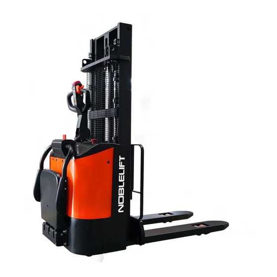
INSTRUCTION MANUAL
Electric Stacker PSE15-C
WARNING
Do not use the electric truck before reading
and understanding these operating
instructions.
NOTE:
• Please check the designation of your
present type at the last page of this
document as well as on the ID-plate.
• Keep for future reference.
Version 08/2020
PSE15-C-SMS-001-EN
xyz
Advertisement
Table of Contents

Related Manuals for Noblelift PSE15-C


Summary of Contents for Noblelift PSE15-C
- Page 1 INSTRUCTION MANUAL Electric Stacker PSE15-C WARNING Do not use the electric truck before reading and understanding these operating instructions. NOTE: • Please check the designation of your present type at the last page of this Version 08/2020 document as well as on the ID-plate.
- Page 2 FORWARD Before operating the electric stacker, read this ORIGINAL INSTRUCTION HANDBOOK carefully and understand the usage of the truck completely. Improper operation of the truck may create a danger situation. This handbook describes the usage of different electric stackers. When operating and servicing the truck, make sure, that it applies to your type.
-
Page 3: Table Of Contents
TABLE OF CONTENTS CORRECT APPLICATION ......................... 3 DESCRIPTION OF THE STACKER ....................4 Overview of the main components ....................4 Main technical data ......................... 6 Description of the safety devices and warning labels (Europe and others, except USA))..... 8 Identification plate ........................... 9 WARNINGS, RESIDUAL RISK AND SAFETY INSTRUCTIONS ............ -
Page 4: Overview Of The Main Components
1. CORRECT APPLICATION It is only allowed to use this electric stacker according to this instruction handbook. The trucks described in this handbook are self-propelled pedestrian controlled electric power stackers, with electrically powered lifting function. The trucks are designed for stacking operations in dedicated racking by lifting and lowering the palletized loads up to the desired lifting heights. -
Page 5: Description Of The Stacker
2. DESCRIPTION OF THE STACKER a. Overview of the main parts Fig. 1: Overview main parts 1. Protective arm 9. Accelerator 2. Platform 10. Multi-function tiller 3. Driving wheel 11. Outer covers 4. Steering wheel 12. Truck body 5. Charging indicator 13. -
Page 6: Main Technical Data
b. Main technical data Fig. 2: Technical data... - Page 7 Table1: Main technical data for standard version Type sheet for industrial truck acc. to VDI 2198 Manufacturer’s type designation 3600 Drive: electric (battery type, mains...), diesel, petrol, fuel gas Battery Operator type (hand, pedestrian, standing, order-picker) Pedestrian Rated capacity/ rated load Q(t) Load centre distance C(mm)
-
Page 8: Description Of The Safety Devices And Warning Labels (Europe And Others, Except Usa)
Lowered mast height Free Lift height Lift height Extended mast height Lift+fork height Designation h1(mm) h2(mm) h3(mm) h4(mm) h3+h13(mm) 1978 1510 1515 1985 1600 One stage mast 2378 1910 1915 2385 2000 1930 2815 3305 2900 Two stage mast 2080 3115 3605 3200... -
Page 9: Identification Plate
d. Identification plate Designation, type Battery weight minimum/ maximum Serial number Nominal power in kW Rated capacity in kg Load center distance Supply voltage in V 10 Manufacturing date Own mass (self weight) in kg without battery 11 Option Name and address of manufacturer) If sold to the EU, here the place of the CE marking Fig. -
Page 10: Warnings, Residual Risk And Safety Instructions
3. WARNINGS, RESIDUAL RISK AND SAFETY INSTRUCTIONS DO NOT • Put foot or hand under or into the lifting mechanism. • Allow other person than the operator to stand in front of or behind the truck when it is moving or lifting/lowering. •... -
Page 11: Commissioning, Transporting, Decommissioning
4. COMMISSIONING, TRANSPORTING, DECOMMISSIONING a. Commissioning Table 2: Commissioning data Type PSE15-C/1600 PSE15-C/3600 Commissioning weight [kg] Dimensions [mm] 1600 3600 After receiving our new stacker or for re-commissioning you have to do following before (firstly) operating the truck: • Check if are all parts included and not damaged •... -
Page 12: Decommissioning
Transportation DURING TRANSPORTATION ON A LORRY OR TRUCK ALWAYS FASTEN THE TRUCK SECURELY Lower the forks and park the truck securely. Fasten the truck according to Fig. 6 by fixing dedicated lashing belts to chassis, Fork carriage and mast, and fasten the other side at the transporting truck. c. -
Page 13: Operation Instructions
6. OPERATION INSTRUCTIONS BEFORE OPERATING THIS TRUCK, PLEASE FOLLOW THE WARNINGS AND SAFETY INSTRUCTIONS (CHAPTER 3). BEFORE OPERATING THIS TRUCK, ENSURE THAT THE LOAD OR OTHER EQUIPMENT NOT CAUSES INSUFFICIENT VISIBILITY! Ensure that the goods are level and stable, and conduct daily inspections. -
Page 14: Lifting
c. Lifting DO NOT OVERLOAD THE TRUCK! THE MAXIMUM CAPACITY IS 1500kg. LIFT ONLY CAPACITIES ACCORDING TO THE RESIDUAL LIFT DIAGRAM. Travel with the lowered forks fully underneath the pallet and press the lifting button (Fig. 7, 18) until you reached the desired lifting height. -
Page 15: Steering
Carefully pull out the emergency button 7 (Fig. 1) and start the truck by activation from pin-code lock (Fig. 7) access. Then move the tiller to the operating zone (‘F’, Fig.10). Turn the accelerator knob to the desired direction forward ‘Fw.’ Or backwards ‘Bw.’(Fig. 10). Control the travelling speed by moving accelerator knob (10) carefully until you reached desired speed. -
Page 16: Battery Charging And Replacement
Before finishing the maintenance work, make sure, that all cables are connected correctly and that there are no disturbing towards other components of the truck. PSE15-C equips with lead-acid battery: 2x12V/ 106Ah, 2x34kg. IT IS ONLY ALLOWED TO USE LEAD ACID BATTERY FOR ECL15B. IT IS ONLY ALLOWED TO USE LITHIUM BATTERY FOR ECL15N. -
Page 17: Charging
Power display: 10 grids indicate 100% charge, each grid represents 10% charge, every 10% discharge with power out of one grid, if the remaining charge is less than 20%, the grids on the display screen flashes. When the battery is charged to the recovery voltage of the indicator, the display screen will show full recovery charge grids. -
Page 18: Regular Maintenance
8. REGULAR MAINTENANCE • Only qualified and trained personnel are allowed to do maintenance on this truck. • Before maintaining, remove the load and lower the forks to the lowest position. • If you need to lift the truck, follow chapter 4b by using designated lashing or jacking equipment. -
Page 19: Lubricating Points
• Check if correct fuses are used, if necessary replace. • Test the audio warning signal • Check the contactors • Check the frame leakage (insulation test) • Check function and wear of the accelerator • Check the electrical system of the drive motor b. -
Page 20: Checking Electrical Fuses
d. Checking electrical fuses Table 5: Size of the fuses Rate FU 01 FU 02 200A Fig. 16: Location of fuses e. Removing, reattaching guarding DO NOT USE THIS TRUCK, IF THE GUARDING IS DAMAGED OR NOT CORRECTLY ASSEMBLED! If the guarding needs to be removed, unscrew carefully. For reattaching place the guarding to its correct position and screw to their original position. -
Page 21: Trouble Shooting
TROUBLE SHOOTING • If the truck has malfunctions follow the instructions, mentioned in chapter 6. Table 6: Trouble shooting TROUBLE CAUSE REPAIR Lift only max. capacity, Load weight too high mentioned on the ID-plate Battery discharged Charge the battery Check and eventually replace the Lifting fuse faulty Load can’t be lifted lifting fuse... -
Page 22: Wiring/ Circuit Diagram
10. WIRING/ CIRCUIT DIAGRAM a. Electrical circuit diagram Fig. 17: Electrical diagram (PSE15-C) - Page 23 Table 7: Description of electrical components Code Item Code Item Battery Horn Controller FU01 80A fuse Pump motor FU02 200A fuse Pump contactor 10A fuse Emergency switch 24V charger Electromagnetic valve Spring cable Micro switch Detong logic module Accelerator Proximity switch (NC) SA SH Proximity switch (NO) K K1...
-
Page 24: Hydraulic Circuit
Hydraulic circuit diagram Fig. 18: Hydraulic circuit diagram Table 8: Description of hydraulic components Code Item Code Item Hydraulic power unit (motor and pump) Throttle valve One-way valve Cylinder Electromagnetic valve Safety valve Relief valve... -
Page 25: Specialized Stipulations For The Usa Market
11. SPECIALIZED STIPULATIONS FOR THE USA MARKET The content in this chapter is specialized for the US-American market. a. Foreword/ Compliance Operating this truck requires knowledge which can be acquired from this instruction handbook. This handbook must be kept available throughout the entire period of use of the industrial truck. IT IS LAW;... -
Page 26: Description Warning Labels (Only For Usa Market)
b. Description of labels and decals (only for USA market) Fig. 19: Warning labels and safety devices (only USA market) A Decal (crane hook) Label (crushing warning) C Label (residual lift capacity) Warning label (warning stay clear stop truck) E Label (identification plate) Label (battery danger) F Decal (read and follow the instructions) Label (electrical devices) - Page 27 Decal (read and follow the instructions) (F) Label (be certified and trained) (J) Decal (oil filling) (G) Label (no riding) (H) Label (battery danger) (L) Label (no standing/riding on/under forks) (N) Label (crushing warning) (I) Label (no adding electrical devices) (M)
-
Page 28: Technical Data For Us Market
c. Technical data for US market Check page 6 for the drawing. Table 9: Main technical data for standard version (USA market) Type sheet for industrial truck acc. to VDI 2198 Manufacturer`s type designation 3600 Drive Battery Operator type Pedestrian Load capacity / rated load Q (lbs) Load center distance... - Page 29 Travel speed, laden/ unladen 2.5/2.6 Lift speed, laden/ unladen 13.4/31.9 Lowering speed, laden/ unladen 28/26.8 Max. gradeability, laden/ unladen 5/10 5.10 Service brake Electromagnetic Drive motor rating S2 60min Lift motor rating at S3 10% 2.95 Battery acc. to DIN 43531/ 35/ 36 A, B, C, no Battery voltage, nominal capacity K5 V/Ah 2x12/106...
-
Page 30: Declaration Of Conformity (Valid, If Sold Within The Eu)
CE-DD-002 12. DECLARATION OF CONFORMITY (valid, if sold within the EU) [GB] CE Declaration of Conformity The signatory hereby declares that the specified machine conforms to the EU Directive 2006/42/EC (Machine Directive) and 2014/30/EU (Electro-Magnetic Compatibility, EMC) including their amendments as translated into national legislation of the member countries. The signatory is individually authorized to compile the technical documents. - Page 31 nacionālajai likumdošanai. Parakstu īpašnieki ir atsevišķi pilnvaroti sastādīt tehniskās dokumentācijas. [N] EU-KONFORMITETSERKLÆRING Undertegnede bekrefter hermed at de enkelte betegnede maskin med kraftdrift tilsvarer de europeiske retningslinjene 2006/42/EC (maskinretningslinje) og 2014/30/EU (elektromagnetisk fordraglighet - EMV) inklusiv disses endringer og den tilsvarende rettsforordning til omsetning av nasjonal rett. Hver undertegnede er fullmektig til å...
Need help?
Do you have a question about the PSE15-C and is the answer not in the manual?
Questions and answers