Table of Contents
Advertisement
Quick Links
INSTRUCTION HANDBOOK
Electric Stacker (PS12/15CB-C)
WARNING
Do not use the electric truck before reading
and understanding these operating
instructions.
NOTE:
• Please check the designation of your
present type at the last page of this
document as well as on the ID-plate.
• Keep for future reference.
Version 06/2020
PS12/15CB-C-SMS-001-EN
1
Advertisement
Table of Contents

Related Manuals for Noblelift PS12/15CB-C


Summary of Contents for Noblelift PS12/15CB-C
- Page 1 INSTRUCTION HANDBOOK Electric Stacker (PS12/15CB-C) WARNING Do not use the electric truck before reading and understanding these operating instructions. NOTE: Version 06/2020 • Please check the designation of your PS12/15CB-C-SMS-001-EN present type at the last page of this document as well as on the ID-plate.
- Page 2 FOREWORD Before operating the stacker, read this ORIGINAL INSTRUCTION MANUAL carefully and understand the usage of the stacker completely. Improper operation could create danger. This manual describes the usage of different electric pallet stackers. When operating and servicing the stacker, make sure, that it applies to your type. Keep this manual for future reference.
-
Page 3: Table Of Contents
Table of Contents CORRECT APPLICATION ......................... 5 DESCRIPTION OF THE PALLET STACKER ..................6 a. Overview of the main parts ....................... 6 b. Main technical data ........................... 7 c. Description of the safety devices and warning labels (Europe and other, except USA) ....10 d. - Page 4 c. Technical data for US market ......................30 12. DECLARATION OF CONFORMITY (valid, if sold within the EU) ............ 32...
-
Page 5: Correct Application
CORRECT APPLICATION It is only allowed to use this electric pallet stacker according to this instruction manual. The stackers described in this manual are self-propelled electric power pallet stackers. The stackers are designed to lift, lower and transport palletized loads. A wrong usage can cause human injuries or can damage the stacker. -
Page 6: Description Of The Pallet Stacker
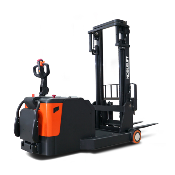
DESCRIPTION OF THE PALLET STACKER Overview of the main parts Fig. 1: Overview main components Platform assembly 10. Accelerator knob (butterfly knob) Cover unit 11. Mid-cover Protective arm assembly 12. Battery cap Protective arm cover 13. Emergency stop button Top cover 14. -
Page 7: Main Technical Data
Main technical data Fig. 2: Technical data... - Page 8 Table1: Main technical data for standard version Type sheet for industrial truck acc. to VDI 2198 Manufacturer’s type designation PS12CB-C PS15CB-C Drive: electric (battery type, mains...), diesel, petrol, Electric fuel gas Operator type (hand, pedestrian, standing, Standing order-picker) Rated capacity/ rated load Q(t) 1200 1500...
- Page 9 Drive motor rating S2 60min Lift motor rating S3 10% Battery according to DIN 43531/35/36 A, B, C, no Battery voltage/ nominal capacity K 24/210 24/270 V/Ah Battery weight Energy consumption according to VDI 2198 0.76 Kwh/h Type of drive unit Sound pressure at the driver’s seat according to <70 dB(A)
-
Page 10: Description Of The Safety Devices And Warning Labels (Europe And Other, Except Usa)
Description of the safety devices and warning labels (Europe and other, except USA) Crane hook label Warning decal: Do not stand under or on the forks C. Load curve sticker D. “No passengers” decal Identification plate (ID-plate) Sticker to read and follow these instructions The truck is equipped with an emergency button (13) which stops all lifting-, lowering-, driving- functions and engages the fail-safe electromagnetic brake when it is pressed. -
Page 11: Warnings, Residual Risk And Safety Instructions
WARNINGS, RESIDUAL RISK AND SAFETY INSTRUCTIONS DO NOT • Lift the load higher than the lift point when operate the stacker outdoors. • Put foot or hand under or into the lifting mechanism structure. • Allow other person than the operator to stand in front of or behind the truck when it is moving or lifting/lowering. -
Page 12: Commissioning, Transporting, Decommissioning
COMMISSIONING, TRANSPORTING, DECOMMISSIONING Commissioning Table 2: Commissioning data Type PS12CB-C PS15CB-C Commissioning weight [kg] 1842 2162 Dimensions [mm] 3600 4500 After receiving our new pallet stacker or for re-commissioning you have to do following before (firstly) operating the truck: • Check if are all parts included and not damaged •... -
Page 13: Decommissioning
Decommissioning For storage, remove the load, lower the truck to the lowest position, grease all greasing points mentioned in this handbook (regular inspection), and eventually protect the truck against corrosion and dust. Remove the batteries and jack the truck safely, so that there will be no crush after storage. For final decommissioning hand in the truck to a designated recycling company. -
Page 14: Parking
PLEASE FOLLOW THE WARNINGS AND SAFETY INSTRUCTIONS (CHAPTER 3) BEFORE PERATING THIS STACKER. MAKE SURE LOADS OR OTHER EQUIPMENT WILL NOT CAUSE POOR VISIBILITY BEFORE OPERATING THIS STACKER. Make sure that the load is placed horizontally and stably and the daily inspection is carried out. The operator must carefully pull emergency button (13) out. -
Page 15: Travelling
Travelling TRAVEL ON INCLINES ONLY WITH THE LOAD FACING UPHILL. DO NOT TRAVEL ON INCLINES MORE THAN SPECIFIED TECHNICAL DATA. TRAVELLING IS ONLY ALLOWED IF THE FORKS ARE LOWERED DOWN TO THE LIFTING POSITION (<300MM). Fig.10: Operating direction After starting the truck by activation from Pin-code panel and carefully pull out the emergency button. Then move the tiller to the operating zone (‘F’, Fig.10). -
Page 16: Braking
Braking THE BRAKING PERFORMANCE DEPENDS ON THE TRACK CONDITIONS AND THE LOAD CONDITIONS OF THE TRUCK The braking function can be activated in several ways: • By moving the accelerator knob (10) back to the initial ‘0’ position or by releasing the knob, the regenerative braking is activated. -
Page 17: Battery Charging And Replacement
BATTERY CHARGING AND REPLACEMENT • Only qualified personnel are allowed to service or charge the batteries. Must follow the instructions of this manual and the explanations of the manufacturer. • The truck is equipped with lead acid battery. • Recycling of batteries undergoes national regulations. Please follow these regulations. •... -
Page 18: Charging
(1) Power display: 10 grids indicate 100% charge, each grid represents 10% charge, every 10% discharge with power out of one grid, if the remaining charge is less than 20%, the grids on the display screen flashes. When the battery is charged to the recovery voltage of the indicator, the display screen will show full recovery charge grids. -
Page 19: Regular Maintenance
REGULAR MAINTENANCE • Only qualified and trained personnel are allowed to do maintenance on this truck. • Before maintaining, remove the load from the forks and lower the forks to the lowest position. • If you need to lift the order picker, please use the specific binding equipment or lifting equipment mentioned in Chapter 4. -
Page 20: Lubricating Points
• Check the contactors • Check the frame leakage (insulation test) • Check function and wear of the accelerator • Check the electrical system of the drive motor Braking system • Check brake performance, if necessary replace brake disc or adjust air gap Battery •... -
Page 21: Check And Refill Hydraulic Oil
Check and refill hydraulic oil The required hydraulic l type is: • H-LP 46, DIN 51524 • Viscosity is 41.4 – 47 • Oil volume: 10L Waste material like used oil, waste batteries or others must be properly disposed and recycled according to the national regulations and if necessary brought to a recycling company. -
Page 22: Trouble Shooting
9. TROUBLE SHOOTING IF THE TRUCK HAS MALFUNCTIONS FOLLOW THE INSTRUCTIONS THAT MENTIONED IN CHAPTER 6. Table 5: Trouble shooting TROUBLE CAUSE REPAIR Load weight is too high Load the truck within rated capacity. Charge the battery. Battery discharged Check and replace the lifting fuse. Lifting fuse faulty Check and refill hydraulic oil. - Page 23 very slowly The electromagnetic brake is engaged. Check the electromagnetic brake. The relating tiller cables are Check the tiller cables and connectors. disconnected or damaged Defective height sensor for reduced Check the sensor. speed at 300mm height Electric system overheated Stop using and cool down the truck.
-
Page 24: Wiring/ Circuit Diagram
WIRING/ CIRCUIT DIAGRAM Electrical circuit diagram Fig. 15: Electrical circuit diagram Table 6: Description of electrical components Code Item Code Item Code Item Battery(24V/210AH) Limit sensor Proximity switch DC power switch Micro switch Keep Pressure retaining valve Speed limit switch FU01 Fuse Tilt up valve... -
Page 25: Hydraulic Circuit Diagram
Hydraulic circuit diagram Fig. 16: Hydraulic circuit diagram(without tilting) - Page 26 Fig. 17: Hydraulic circuit diagram(with tilting)
-
Page 27: Specialized Stipulations For The Us- American Market
SPECIALIZED STIPULATIONS AMERICAN MARKET The content in this chapter is specialized for the US-American market. Foreword/ Compliance Operating this truck requires knowledge which can be acquired from this instruction handbook. This handbook must be kept available throughout the entire period of use of the industrial truck. IT IS LAW;... -
Page 28: Description Warning Labels (Only Us- Market)
Description warning labels (only US- market) Fig. 18: Warning labels and safety devices (only USA) A Crane hook label I Sign danger being crushed K Sign not under, on forks C Residual lift capacity sticker E Identification plate (ID-plate) L Sign danger battery Sticker read and follow these... - Page 29 Sign read and follow this instruction (F) Sign warning stay clear stop truck (M) Sign not under, on forks (K) Sign danger not riding (H) Sign danger battery (L) Sign warning electrical devices (N) Sign danger being crushed (I)
- Page 30 Technical data for US market Drawing see fig.2 Table 7: Main technical data for standard version(US market) Type sheet for industrial truck acc. to VDI 2198 PS12CB-C PS15CB-C Manufacturer`s type designation Drive Battery Operator type Pedestrian Load capacity / rated load Q (lbs) 2640 3300...
- Page 31 Drive motor rating S2 60min Lift motor rating at S3 10% 2.95 Battery acc. to DIN 43531/ 35/ 36 A, B, C, no V/Ah 24/210 24/270 Battery voltage, nominal capacity K5 477.4 633.6 Battery weight Energy consumption acc. to VDI cycle kWh/h 0.76 AC- Speed Control...
- Page 32 CE-DD-002 DECLARATION OF CONFORMITY (valid, if sold within the EU) [GB] CE Declaration of Conformity The signatory hereby declares that the specified machine conforms to the EU Directive 2006/42/EC (Machine Directive) and 2014/30/EU (Electro-Magnetic Compatibility, EMC) including their amendments as translated into national legislation of the member countries. The signatory is individually authorized to compile the technical documents.
- Page 33 nacionālajai likumdošanai. Parakstu īpašnieki ir atsevišķi pilnvaroti sastādīt tehniskās dokumentācijas. [N] EU-KONFORMITETSERKLÆRING Undertegnede bekrefter hermed at de enkelte betegnede maskin med kraftdrift tilsvarer de europeiske retningslinjene 2006/42/EC (maskinretningslinje) og 2014/30/EU (elektromagnetisk fordraglighet - EMV) inklusiv disses endringer og den tilsvarende rettsforordning til omsetning av nasjonal rett. Hver undertegnede er fullmektig til å...
Need help?
Do you have a question about the PS12/15CB-C and is the answer not in the manual?
Questions and answers