
Related Manuals for Noblelift PS 12 TSL


Summary of Contents for Noblelift PS 12 TSL
- Page 1 Service & Maintenance Manual PS 12 16 18TSL 03/2019 PS XXN-SMS-001-CHN Version 02/2021...
- Page 2 Foreword Proper operation, maintenance, trouble shooting and repair are necessary for long-term use of the vehicle while ensuring that the vehicle does not break down again. The purpose of this service manual is to provide the necessary information especially for inspection, repair and maintenance. The main material of this car is steel, which can be completely recycled.
-
Page 3: Table Of Contents
Content 1.GENERAL ............................... 4 1.1 Introductions – Maintenance safety precautions ................4 1.2 Measurement conversions ......................7 2.Sepcification ............................14 2.1 Overview of the main components ..................... 14 2.2Main technical data ........................15 3. Electrical system ..........................18 3.1 Electrical circuit diagram ......................18 3.2Cable System .......................... - Page 4 10.1 Replace PCB motherboard ....................... 76 10.2 Replace air spring (refer to handle assembly drawing) ............77 10.2.1 Mounting air spring ........................ 78 10.3 Replace the interlock switch ..................... 79 11. Driving wheel ............................81 11.1 Replace the small wheel ......................81 11.2 Replace lubricating oil in drive wheel gearbox .................
-
Page 5: General
1.GENERAL 1.1 Introductions – Maintenance safety precautions Maintenance work may cause injuries. Always take care to perform work safe, at least observing the following. It is of utmost importance that maintenance personnel pay strict attention to these warnings and precautions to avoid possible injury to themselves, others or damage to the equipment. A maintenance program must be followed to ensure that the machine is safe to operate. - Page 6 Battery should always be disconnected during replacement of electrical components. Always use the grades of grease and oil recommended by NOBLELIFT choose the viscosity specified for the ambient temperature. Exhaust gas is dangerous provide ventilation when working in a closed space.
- Page 7 When changing the oil or fitter, check the drained oil and filter for any signs of excessive metal particles or other foreign materials. Always use NOBLELIFT genuine parts for replacement. ENSURE REPLACEMENT PARTS OR COMPONENTS ARE IDENTICAL OR EQUIVALENT TO ORIGINAL PARTS OR COMPONENTS. ...
-
Page 8: Measurement Conversions
1.2 Measurement conversions Length Unit mile 0.01 0.00001 0.3937 0.03281 0.01094 0.000006 0.001 39.37 3.2808 1.0936 0.00062 100000 1000 39370.7 3280.8 1093.6 0.62137 2.54 0.0254 0.000025 0.08333 0.02777 0.000015 30.48 0.3048 0.000304 0.3333 0.000189 91.44 0.9144 0.000914 0.000568 mile 160930 1609.3 1.6093 63360... - Page 9 Unit kgf/cm2 Pa=N/m2 lbf/in2 lbf/ft2 kgf/cm2 0.98067 98066.5 98.0665 14.2233 2048.16 1.01972 100000 14.5037 2088.6 Pa=N/m2 0.00001 0.001 0.001 0.00015 0.02086 0.01020 0.01 1000 0.14504 20.886 lbf/in2 0.07032 0.0689 6894.76 6.89476 lbf/ft2 0.00047 0.00047 47.88028 0.04788 0.00694 kgf/cm2=735.56 Torr(mmHg)=0.96784atm Standard tightening torque The following charts give the standard tightening torques of bolts and nuts.
- Page 10 Classification Bolt type Bolt size Torque kgf · m (lbf · ft) Torque kgf · m (lbf · ft) 0.6 ± 0.06 1.7 ± 0.2 5/16 1.2 ± 0.12 3.0 ± 0.3 2.0 ± 0.20 5.6 ± 0.5 7/16 3.2 ± 0.32 8.9 ±...
- Page 11 PF THREAD Thread Torque (kgf·m) 1.1 ± 0.1 2.6 ± 0.2 4.6 ± 0.3 8.5 ± 0.4 19 ± 1.0 33 ± 2.0 TORQUE FOR SWIVEL NUT WITH O-RING Tube O.D (inch) Thread (in) Torque (kgf·m) UN 13/16 - 16 9.5 ±...
- Page 12 Conv Non–SI Conv Unit Factor APPROXIMATE CONVERSIONS Unit Factor Unit Torque Newton meter (N·m) × 8.9 = ln·in × 0.113 = N·m Newton meter (N·m) × 0.74 = lb·ft. × 1.36 = N·m Newton meter (N·m) × 0.102 = kg·m ×...
- Page 13 Remove pin Install pin Loose lock Two-hole lock Four-hole lock Remove pin...
-
Page 15: Sepcification
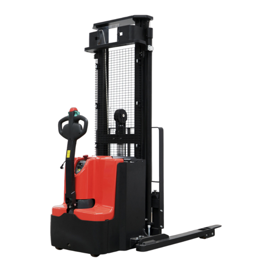
2.Sepcification 2.1 Overview of the main components Chassis Main cover Tiller Emergency switch Belly button Accelerator Battery cover Protective mesh Mast 10. Key switch 11. Indicator 12. Hydraulic system assembly 13. Load backrest 14. fork carriage 15. Fork 16. Load roller assembl... -
Page 16: Main Technical Data
2.2Main technical data Type sheet for industrial truck acc. to VDI 2198 Manufacturer`s type designation (PS12TSL3600) (PS16TSL4600) (PS18TSL4600) Power (battery ,diesel, petrol, Battery gas, manual) Operator type Pedestrian Load Capacity / rated load Q(t) Load centre distance C(mm) Load distance ,centre of drive x(mm) axle to fork 1331... - Page 17 Wheels, number 1x+2/4 front/rear(x=driven wheels) b10(mm) Track, front h1(mm) Lowered mast height 2308 2108 2228 Free Lift height h2(mm) 1760 1520 1520 Lift height h3(mm) 3560 4530 4530 h4(mm) Extended mast height 4088 5088 5208 Height of tiller in drive position h14(mm) 890/1420 min./ max.
- Page 18 Lifting + Lowered mast Free Lift Lift Extended minimum height Features height height height mast height of fork h1(mm) h2(mm) h3(mm) h4(mm) h3+h13(mm) PSK (PS12TSL) Two-stage 1958 2830 3380 2880 Mast 2108 3130 3680 3180 Standard Lift 2308 3530 4080 3580 1958 1410...
-
Page 19: Electrical System
3. Electrical system 3.1 Electrical circuit diagram Code Item Description Code Item Description The handle Pump motor capacitance Traction motor Traction controller Electricity meter FU01 Fuse 350A Magnetic switch FU1/FU2 Fuse 10A Proximity switch battery DC power switch The horn Micro switch Proximity switch Key switch... - Page 20 Manual-steering Electrical circuit diagram Item Code. Item Description Item Code Item Description handle Pump motor capacitance Traction motor Traction controller Electricity meter FU01 Fuse 350A Magnetic switch FU1/FU2 Fuse 10A Proximity switch battery DC power switch horn Micro switch Proximity switch Key switch relay diode...
- Page 21 solenoid valve Angle sensor USB power supply...
-
Page 22: Cable System
3.2Cable System Main loop wiring harness The fuse1: 10A The fuse2 : 10A The fuse01 : 350A Item Code Item Description Qty. Note 534833010008 Main power harness 534833010009 cable 534833010006 cable 534833010007 cable 534833010013 cable 534833010003 cable 534833010005 cable 534833010004 cable... -
Page 23: Drive Wheels
3.3 drive wheels Item Code Item Description Qty. Note 535998510001 Brake 535998520000 Locating Ring 535998520001 Division Plate 535998520002 Screw M8x175 535998510002 Sensor 535998520003 M6x8 535998520004 Safety Element 535998520005 Feather Key 5x5x14 535998520006 535998520007 O-Ring 535998510003 Motor 535998520014 Gear 535998520008 535998520009 O-Ring 146x3 910200200060... - Page 24 535998520013 Bearing wheel assembly Item Code Item Description Qty. Note 534717020001 910600400017 Spring Pin 4x35 534717020002 Plate 940600500004 Washer 910700200019 Bearing 6204-2RS 940300300009 WheelΦ84x70 940500200003 Bushing 532998510001 Wheel 534717001001 Bearing wheel assembly...
-
Page 25: The Pump Station System4.Battery Using
3.4 The pump station system4.Battery Using Item Code Item Description Qty. Note 534798510006 Motor 3.2KW 534798510007 Valve Block 534798520024 Magnetic Valve 534798520025 Coil 534798520026 Carbon Brush... -
Page 26: The Storage Battery
4. The Storage Battery Power supply • Only professionals are allowed to repair or charge the battery. Be sure to follow this manual and the battery manufacturer's instructions • The batteries used are lead-acid batteries • Battery recycling is subject to national regulations. Please comply with these regulations •... -
Page 27: Battery Replacement
•The weight of the battery has a certain impact on the vehicle's operating behavior. Please consider the maximum operating temperature of the battery. 4.1 Battery replacement Park the vehicle safely, close the stacker with the key (8) and press the emergency stop switch (6). Open the lid of the battery case, remove the hinge, and remove the lid. - Page 28 2. Unplug the battery 3. Use a tool to connect here, such as a hook, and then remove the battery Side-shift 1. Open the lid of the battery case 2. Unplug the power plug 3. Unscrew the bolt with the 5mm inner hexagon 4.
-
Page 29: Maintenance Of Batteries (Lead-Acid Batteries)
5. Take out the battery according to the direction indicated by the arrow, and the installation process is the reverse process of disassembly. 4.2 Maintenance of batteries (lead-acid batteries) 1. Cause of water supply of battery The battery recharge is due to the electrolytic effect of the battery at the later charging stage, which makes the moisture part of the electrolyte electrolyze. - Page 30 1.Unplug battery switch 2.Uncap plate bus-bar 3. Electrolyte lever is lower than bus-bar, then add 4. Can’t see the bus-bar for some models distill water Liquid lever is 10mm lower than plate, then add distill water...
-
Page 31: Battery Display
Max lever Standard lever 5.Use a plastic funnel to add water. 6. add-water lever 4.3 Battery display The discharge condition is represented by 10 black block display segments. 图.13: 电池电量显示器 Only when the battery is fully charged correctly, the LED10 grid black block on the far right is all displayed. As the battery's charge status drops, the power display block lights decrease in turn, but only one at a time. -
Page 32: Description Of Electricity Meter
4.3.1 Description of electricity meter... -
Page 33: The Charger
5. The Charger 5.1 an overview of the charger This charger is suitable for charging common lead-acid batteries on various electric vehicles such as electric pallet truck, electric moving truck, electric forklift truck, electric lift truck, electric tour bus, etc. 5.2 Main technical data Type CBZ3F... -
Page 34: Charging
5.3 charging • Charge only with the included charger • Please fully understand the contents of the charger instruction manual before using the charger • Please comply with these rules • The charging room must be well ventilated. • Full charging can only be viewed from the discharge display. To control this situation, interrupt the charging process and start the vehicle Park the vehicle in a special secure area with dedicated power supply. -
Page 35: Controller
6.Controller 6.1 Controller Unit Item Description Qty. Note Controller COMBIACX24V/240A+270A contactor SW180B-4 DC24V ACR01F-F-1AD DC24V relay Bolted fuse CNL 350A CH MIC Plug-in type fuse... -
Page 37: Meter
7.Meter Display Assembly Item Description Qty. Note. ZAPI F04264-MDI CAN Electricity meter Universal key switch LKS-101A DC power switch ZDK32-350 8. Replace electrical parts Power must be disconnected before replacing electrical parts Note: Lower the fork to the bottom before servicing, then turn off the key switch and disconnect the power. - Page 38 1.Remove the bolts shown below with an inner 6mm 2. Disconnect the power supply of the vehicle, i.e. hexagon wrench. unplug the battery connection port in the picture below. 3. Unscrew the four screws with the 6mm inner 4. Unplug three plugs hexagon wrench, and cut off the binding belt of the surrounding wiring harness 5.
-
Page 39: Replace The Electric Meter
emergency stop switch box with a 14mm wrench, and then remove the wiring 8.1 Replace the electric meter 1. Unscrew the two fixed nuts of the meter by hand 2. Remove metal ring 3. Replace the electric meter... -
Page 40: Replace The Emergency Button
8.2 Replace the emergency button 1. Unscrew the two screws of the emergency button 2. Remove the screw and then remove the with a cross screwdriver mushroom head 3. Unscrew the screw with a cross screwdriver Separate the integrated blade panel from the instrument fixing plate 5. -
Page 41: Replace The Universal Key Switch
7. Press the buckle on both sides of the micro switch by hand to unplug the micro switch, the installation process and the reverse process of the above process. 8.3 Replace the universal key switch 1. Use a wrench to unscrew the retaining nut on the 2. -
Page 42: Replace Fuse 1, Fuse 2, Fuse 01 (Refer To 3.1 Circuit Diagram)
8.4 Replace fuse 1, fuse 2, fuse 01 (refer to 3.1 circuit diagram) 1. Open the fuse box 2. After opening the fuse box, take out the old fuse, replace the new fuse, the installation process and the reverse process of the above process. Fuse Fuse1 Fuse2... -
Page 43: Replace The Contactor (Refer To 3.7 Electronic Control Module 4)
1. Unscrew the nut with a 13mm open wrench, remove the fuse, and replace it with a new fuse, the installation process and the reverse process of the above process. 8.5 Replace the contactor (refer to 3.7 Electronic Control Module 4) 1. - Page 44 3 Remove the copper bar 4. Unscrew the bolt with a 13mm open end wrench 5. Remove the copper bar 6. Unscrew the two screws with a cross screwdriver...
- Page 45 7. Remove the contactor with mounting frame 8. Unscrew two screws with a screwdriver. 9. Remove the mounting frame, and the contactor can be replaced. The installation process is the reverse process of disassembly...
-
Page 46: Replace The Electric Control
8.6 Replace the electric control 1. Remove the wiring on the electronic control in turn, pull out the connector, and note down the different ports corresponding to different wiring 2. Unscrew the five screws V, U, W, -P and -B with a 10mm open wrench, and remove the wiring in turn... -
Page 47: Replace The Relay
3. Unscrew four controller fixing screws with a cross screwdriver, that is, remove the controller, the installation process is the reverse process of disassembly 8.7 Replace the relay 1. Unscrew the setting screw with a cross screwdriver... - Page 48 2. Remove the relay and pull out the wiring 3. Relays can be replaced, and the installation process is the reverse process of disassembly...
-
Page 49: Replace Micro Switch
8.8 Replace micro switch 1. 1. Unscrew the bolt with a cross screwdriver and remove the micro switch. 2. Remove shell with 2mm inner hexagon 3. Remove the wiring with a cross screwdriver and it can be replaced... -
Page 50: Replace The Magnetic Switch
8.9 Replace the magnetic switch 2. Unplug the wire harness connector at the other end of the magnetic switch, and cut the tie that binds the wire harness, that is, remove the magnetic switch and replace it. 8.10 Replace wiring harness Pay attention to the corresponding position of each plug when replacing, and do not insert it wrong when installing. - Page 51 2. Unplug and remember the line number 3. Unscrew the screw with 13mm wrench, unplug the plug, and write down the line number 4. Unplug the plug and write down the line number. The position of the line number is shown in the table on...
- Page 52 the right 5. Unscrew the relay with a cross screwdriver, unplug the plug, 5-3- 9-7- 5-3-1 6. Remember the plug corresponding to each line number, as shown in the picture on the right.
- Page 53 7. Unplug the two plugs on the speaker and write down the line number 8. Unscrew the screw with 13mm wrench, remove the wiring, and write down the wiring number 9. Unscrew the screws with a 13mm wrench, remove the wiring, and write down the wiring number.
- Page 54 10. Unplug all plugs on the right side, which are one-to-one corresponding. 11. Remove the instrument panel by unscrewing the four screws with a 6mm inner hexagon wrench.
- Page 55 12. Unplug the plug one by one and write down the line number 13. Unplug each plug in turn. This plug is one-to-one 14. Unscrew the wire harness holder with a 14mm corresponding cross screwdriver...
-
Page 56: Hydraulic System
15. The wiring harness can be removed and replaced 9. Hydraulic system The hydraulic circuit 9.1 Replace the pump station The pallet rack must be lowered before replacement to allow the hydraulic oil in the tubing to return to the hydraulic tank of the pump station. 1. - Page 57 2. Remove the hydraulic tubing with 22m and 22mm 3. Unplug the connector by hand open end wrenches. Note: hydraulic oil will leak out when removing the tubing. It is recommended to put back yarn or rag on the pad when removing the tubing.
-
Page 58: Replace Hydraulic Oil
9.2 Replace hydraulic oil 1. Take out the oil pump, unscrew the cap of the oil tank, waste oil can be poured out, then the oil tank can be installed to the car, the installation process is the reverse process of disassembly. 3. -
Page 59: Replace The Filter
Check and refill the hydraulic fluid The type of hydraulic oil required is: • H-LP 46, DIN 51524 • Viscosity is 41.4 -- 47 • According to the model, the amount of oil is 6.0~9.5L Waste materials such as waste oil, batteries or other materials must be treated and recycled according to national regulations, and if necessary, sent to the recycling company for recycling. -
Page 60: Replace Carbon Brush
2. After removing the oil pump, the filter can be replaced 9.4 Replace carbon brush 1. Unscrew the bolt with a 10mm open end wrench 2. Lift the cover. -
Page 61: Adjust Oil Pump Pressure
3. Unscrew the screw with a cross screwdriver, then take out the carbon brush and replace it. The installation process is the reverse of the above process. 9.5 Adjust oil pump pressure 1. Unscrew the horn fixing bolt and remove the horn 2. -
Page 62: Replace The Outer Oil Cylinder
3. Adjust the pressure of the oil pump with a 6 mm 4. Tighten bolts with a 24 mm hexagon socket inner hexagon wrench wrench 9.6 Replace the outer oil cylinder The outer cylinder on the right 1. Remove the oil pipes at the lifting cylinder on both sides with 19mm open spanner. Note: hydraulic oil will leak out when removing the oil pipes. - Page 63 2. Use a 12mm wrench to remove both sides of the 3. Remove the bolt at the top of the oil cylinder by the return tubing 12mm inner hexagon 4. Using the 6mm inner hexagon screw down the 5. Remove the fixing bolt of the cylinder base with a cylinder pressure plate fixing bolt 12mm inner hexagon wrench.
- Page 64 6. Remove the oil cylinder, and the installation process is the reverse of the above process The outer cylinder on the left 1. Remove the oil pipe at the bottom of the cylinder 2. Remove the top oil pipe of the cylinder with a with a 22mm open spanner 22mm open end wrench...
- Page 65 3. Remove the two bolts fixed between the top of the 4. Remove the four bolts on the press plate of the left left and right oil cylinders and the door frame with the and right oil cylinders with the 6mm inner hexagon 12mm inner hexagon 5.
-
Page 66: Replace The Middle Oil Cylinder
9.7 Replace the middle oil cylinder 1. Knock down the spring clamp with the punch and remove the protection plate 2. Unscrew the oil pipe at the bottom of the middle oil 3. Remove split pin cylinder with a 22mm open spanner... - Page 67 4. Remove the pin shaft and remove the chain 5. Unscrew the hoop bolt with a 13mm open wrench and take the hoop...
- Page 68 6. Remove the middle oil cylinder 7. Remove the snap with the snap pliers 8. Remove sprocket shaft...
-
Page 69: Replace The Sealing Ring Of The Outer Oil Cylinder (Outer Cylinder On The Right)
9. Remove the side cover with 12mm inner hexagon wrench, and then remove all parts for replacement and maintenance. The installation process is the reverse process of disassembly. 9.8 Replace the sealing ring of the outer oil cylinder (outer cylinder on the right) 1. - Page 70 2. Remove the new o-ring with a small screwdriver 3. Use a screwdriver to remove the dust ring 4.Take out sealing ring used for shaft 5. Take out the Stepseal, the oil cylinder head sealing ring can be disassembled and replaced The left cylinder...
- Page 71 1. Unscrew the oil cylinder head with a crescent 2. Pull out the piston rod. wrench. 3. Remove the piston with pipe tongs. Heat the connection between the piston and the piston rod before using the pipe tongs because there is threaded glue inside.
- Page 72 4. Remove oil cylinder cap 5. Use a small screwdriver to take out the new O-ring, 6.Take out the dust ring with a screwdriver 7. Take out the the sealing ring used for shaft 8. Take out the stepseal, the cylinder head sealing ring can be disassembled and replaced...
-
Page 73: Replace The Sealing Ring Of The Middle Cylinder
9.9 Replace the sealing ring of the middle cylinder 1. Remove the oil cylinder head with pipe tongs after removing the middle oil cylinder according to instruction 9.6. 2. Pull out the piston rod and remove the shaft at the bottom of the piston rod with the support ring... - Page 74 3. Use a small word screwdriver to take out the dust ring, retaining ring and Y-type sealing ring in the cylinder head.
- Page 75 4. Remove the O-ring and retaining ring on the cylinder head to repair the entire tubing. The installation process is the reverse process of disassembly.
-
Page 76: Tiller
10.Tiller Handle assembly... -
Page 77: Replace Pcb Motherboard
10.1 Replace PCB motherboard 1. Unscrew the outer cover screw with 6mm inner 2. After unscrewing the screw, carefully open the hexagon wrench handle housing and unplug the connecting plug 3. Unscrew the screw fixing the drive switch with a 4. -
Page 78: Replace Air Spring (Refer To Handle Assembly Drawing)
5.Remove the retaining screw with a Phillips head 6. Remove the old PCB board and unplug the plug in screwdriver turn. The installation process is the reverse process of the above process. 10.2 Replace air spring (refer to handle assembly drawing) 1. -
Page 79: Mounting Air Spring
4. Remove gas spring 10.2.1 Mounting air spring 1. Put the gas spring into the handle and tighten the 2. Use the iron rod to Jack up the air spring and upper bolt tighten the bolt to the bolt hole... -
Page 80: Replace The Interlock Switch
10.3 Replace the interlock switch 1. Unscrew the bolt with 2mm inner hexagon wrench 2. Use a 6mm hexagon socket wrench to unscrew the housing 3. Open the handle housing 4.Unplug the connector (pay attention to the harness number) - Page 81 5. Remove the entire switch 6. Unscrew the screw with a cross screwdriver 7. The interlock switch can be replaced...
-
Page 82: Driving Wheel
11. Driving wheel 11.1 Replace the small wheel 1. Place the jack on the side of the drive wheel to lift the 2. Rotate the handle to this position body. 3. Unscrew 5 fixing bolts with 17mm socket wrench through the repair hole on the car body. Due to the small area of the hole, before each screw is unscrewed, it is necessary to control the driving wheel rotation through the handle and align the bolt that needs to be unscrewed with the maintenance hole so that the socket wrench can unscrew the bolt. - Page 83 4. Remove the wheel by unscrewing five retaining bolts. 5. Take out the driving wheel from the bottom and replace it. The installation process is the reverse process of disassembly.
-
Page 84: Replace Lubricating Oil In Drive Wheel Gearbox
11.2 Replace lubricating oil in drive wheel gearbox 1.There is an oil injection hole on the front of the 2. There is an oil drain hole at the bottom of the driving wheel driving wheel. 3. Raise the car to a certain height with a jack 4. -
Page 85: Replace The Sensor
5. Use a 7 mm hexagon socket wrench to unscrew the 6. Lubricating oil through tubing. The lubricant used is oil hole bolts 85W/90 GL-5 heavy duty vehicle gear oil. 11.3 Replace the sensor 1. Unscrew the fixing bolt with 4mm inner hexagon wrench... - Page 86 2. Unplug the sensor 3. Take out the connecting plug from the cable mounting frame. 5. Separate the plug, 6. Use diagonal pliers to cut the tie that binds the wire harness.
-
Page 87: Braking Part
7. Remove the sensor and it can be replaced. The installation process is the reverse process of disassembly 11.4 Braking part 1. Two bolts are screwed into the bolt hole of the brake with a 4mm hexagon wrench. The size of the bolt is M6 ×... - Page 88 2. Unscrew the 3 bolts of installing the brake with 4mm inner hexagon wrench 3. Unplug the plug and cut the tie...
- Page 89 4. Take out the brake, and the installation process is the reverse process of disassembly. Brake clearance adjustment: use 4mm hexagonal wrench to twist the three screws, use the feeler to measure the brake clearance, control at 0.3mm. The three bolt fixing points need to be measured one by one by a feeler to ensure that the clearance is 0.3mm.
-
Page 90: Steering Wheel
12.Steering wheel Item Code Item Description Note 910200200076 Screw M10x25 910400500007 Spring Washer 910400100007 Flat Washer 505616510002 Plate 910700500002 Bearing 3205A-2RS 910401400016 Circlip... -
Page 91: Maintenance Of Wheelset
505616510001 Wheel Carrier 505616510000 Caster Assembly 941100200002 Bolt M12x100 910300500006 940400500007 Spring Φ43Xφ9x62 505616520000 Spring 940500100002 Bushing 505616510003 Whirling Arm 910100100038 Bolt M10x80 505616520011 Dust Cap 505616520012 Check Ring 505616520013 Bushing 910700200019 Bearing 6204-2RS 940300300018 WheelΦ100x40 505616520007 Retaining Ring 941100300001 Screw M6x14 910600100004... -
Page 92: Maintenance Steering Group
2. Punch the axle out 3. When the axle is removed, the axle and other components of the wheel group can be replaced. The installation process is the reverse process of disassembly 12.2 Maintenance steering group 1. Remove the clamp spring with clamp pliers... - Page 93 2. Remove the wheel frame with punch 3. Take out the clamping spring at the bottom of the 4. Take out both axles with punch. bearing seat with clamping spring pliers. 5. Take out the axle, sleeve, clamp spring and other parts, can be replaced and maintained, the installation process is the reverse process of disassembly.
-
Page 94: Bearing Wheel
13 Bearing wheel Item Code Item Description Qty. Note 534717020001 910600400017 Spring Pin 4x35 534717020002 Plate 940600500004 Washer 910700200019 Bearing 6204-2RS 940300300009 WheelΦ84x70 940500200003 Bushing 532998510001 Wheel 534717001001 Bearing wheel assembly... -
Page 95: Replace The Bearing Wheel
13.1 Replace the bearing wheel 1. First lift the tray rack to a certain height 2.Jack the car to a certain height 3. Place the body on the repair rack and remove the 4. Remove the axle and remove the entire component. elastic cylindrical pin with a punch. - Page 96 5.Take out the elastic pin with punch 6. Take out the axle and the wheel 7. Take out the two bearings with the punch and then repair and replace them. The installation process is the reverse process of disassembly.
-
Page 97: The Chain
14. The chain 14.1 Replace the chain 1. Lift the tray rack and pad it with wood, so that the chain can reach the state of no stress 2. Remove the cotter pin from the top of the chain 3. Remove pin shaft... - Page 98 4. Take out the split pin at the bottom of the chain 5. Take out the pin shaft 5. Remove the chain and replace it. The installation process is the reverse process of disassembly...
-
Page 99: Maintain The Chain
14.2 maintain the chain 1. In the long-term use of products, there will be a loose chain phenomenon, we need to use two 24mm open-ended spanner to tighten the chain bolt, so that the pallet in the lowest position of the chain is still stressed. -
Page 100: Mast System
15.Mast System 15.1 Remove the mast 1. Remove split pin 2. Pull out the latch 3. Unscrew the fixing bolt at the top of the oil cylinder 4. Raise the door frame. with a 12mm inner hexagon wrench... - Page 101 5. Raise the tray rack 6. Lower tray rack 7. Raise the maste and remove the tray frame.
-
Page 102: Replace The Roller
15.2 Replace the roller The whole mast system has the same roller, which will be damaged in the process of use and needs to be replaced. 1. Remove the snap spring with the snap pliers 2. Remove the gasket 3. Remove the roller... - Page 103 4. Use the punch to remove the roller so that it can be replaced 15.3 adjustable roller In the use process, the gap between the portal frame and the portal frame will become larger and need to be adjusted. 1. Open the locating pin...
- Page 104 2. With a word screwdriver screw bolts to adjust, also desirable bolt, for replacement.
-
Page 105: Lable
16 Lable Label (European ) Item Code Item Description Qty. Note 941200300001 Label 941200100004 Label 534847520000 Lable 941200100006 Lable 534847020001 CE Lable 941200300002 Label 941200300003 Lable 941200300018 Lable... - Page 106 Label (American) Item code Item Description Qty. Note 941200300001 Label 534847520000 Label of Load Capacity Diagram 941200300002 Label 941200300003 Label 941200300018 Label 941200100014 Label 941200100009 Label 941200100013 Label 941200100010 Label 941200100016 Label...
-
Page 107: Maintenance List
17.Maintenance list Maintenance list Intervals(Month) Hydraulic system Check hydraulic cylinder if there is noise and leakage of piston Check hydraulic connectors and tubing if there is damage and leakage Check hydraulic oil level and recharge if necessary Add hydraulic oil after 12 months or 1500 hours of work ... - Page 108 Check if main cable is damage Check startup protection procedures during charging Function Check Horn Check electromagnetic valve Check emergency brake Check reverse braking and regenerated braking Check belly button Check steering Check Lift up and down ...
- Page 109 Check and finally fill with hydraulic Hydraulic oil level is too low fluid Check the sealing of tubing and The spill cylinder The height limiting micro switch is wrong Check and repair the microswitch Check and verify that the port is Controller driver port is damaged working and replace the controller Check whether the rise button on...
- Page 110 Inspect and replace the heat The thermal sensor is out of order sensor if necessary Check and verify the controller Controller parameters do not match parameters Check and finally replace the Interlock switch damaged interlock switch Check and eventually replace the Main contactor damaged main contactor The stacker's electric meter...
Need help?
Do you have a question about the PS 12 TSL and is the answer not in the manual?
Questions and answers