Table of Contents
Advertisement
Quick Links
INSTRUCTION HANDBOOK
Electric Stacker PS30RM
WARNING
Do not use the electric truck before reading
and understanding these operating
instructions.
NOTE:
• Please check the designation of your
present type at the last page of this
document as well as on the ID-plate.
• Keep for future reference.
Version 08/2015
PS 30RM-SMS-001-EN
Advertisement
Table of Contents

Related Manuals for Noblelift PS30RM


Summary of Contents for Noblelift PS30RM
- Page 1 INSTRUCTION HANDBOOK Electric Stacker PS30RM WARNING Do not use the electric truck before reading and understanding these operating instructions. Version 08/2015 NOTE: PS 30RM-SMS-001-EN • Please check the designation of your present type at the last page of this document as well as on the ID-plate.
- Page 2 FOREWORD Before operating the electric stacker, read this ORIGINAL INSTRUCTION HANDBOOK carefully and understand the usage of the truck completely. Improper operation could create danger. This handbook describes the usage of different electric stackers. When operating and servicing the truck, make sure, that it applies to your type.
-
Page 3: Table Of Contents
TABLE OF CONTENTS 1. CORRECT APPLICATION .................... 4 2. DESCRIPTION OF THE STACKER ................5 a. Overview of the main components ................5 b. Main technical data ....................6 Description of the safety devices and warning labels (Europe and other, excepting USA) .......................... - Page 4 11. SPECIALIZED STIPULATIONS FOR THE US- AMERICAN MARKET ..... 24 a. Foreword/ Compliance ..................... 24 b. Description warning labels (only US- market) ............25 Technical data for US market ................... 28 12. DECLARATION OF CONFORMITY (valid, if sold within the EU) ........ 30...
-
Page 5: Correct Application
1. CORRECT APPLICATION It is only allowed to use this electric stacker according to this instruction handbook. The trucks described in this handbook are self propelled pedestrian controlled electric power stacker, with electrically powered lifting function. The trucks are designed for stacking operations in dedicated racking by lifting and lowering the palletized load up to the desired lifting height. -
Page 6: Description Of The Stacker
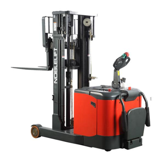
2. DESCRIPTION OF THE STACKER Overview of the main components Fig. 1: Overview main components Platform 11. Protective screen Main cover 12. Protective board Protective arm cover 13. Middle cover Protective arm 14. Battery cover Upper cover 15. Load backrest Emergency button 16. -
Page 7: Main Technical Data
Main technical data Fig. 2: Technical data Table1: Main technical data for standard version Technical data sheet for industrial truck acc. to VDI 2198 PS 15RM Manufacturer`s type designation 1600 1800 3000 3600 4500 Power (battery ,diesel,petrol Battery gas,manual) Operator type Pedestrian Load Capacity / rated load Q (t) -
Page 8: Description Of The Safety Devices And Warning Labels (Europe And Other, Excepting Usa)
Tread, front (mm) Tread, rear (mm) Tilt of mast/fork carriage ° forward/backward Lowered mast height (mm) 2196 2396 2096 1796 2096 Free Lift height 1600 1800 — 1200 1500 Lift (mm) 1600 1800 3000 3600 4500 Extended mast height (mm) 2485 2685 3885... -
Page 9: Identification Plate
A. Crane hook label B. Warning decal: Do not step under or on the forks C. Residual lift capacity sticker D. Never reach through E. Identification plate (ID-plate) Sticker to read and follow these instructions G. ‘No passengers’ decal J. Sign oil filling point The truck has an emergency button (6) which stops all lifting-, lowering-, driving- functions and engages the failsafe electromagnetic brake when it is pushed. -
Page 10: Warnings, Residual Risk And Safety Instructions
3. WARNINGS, RESIDUAL RISK AND SAFETY INSTRUCTIONS DO NOT • Drive outside the stacking operation with a lifted load higher than the lifting point. • Put foot or hand under or into the lifting mechanism. • Allow other person than the operator to stand in front of or behind the truck when it is moving or lifting/lowering. -
Page 11: Commissioning, Transporting, Decommissioning
4. COMMISSIONING, TRANSPORTING, DECOMMISSIONING Commissioning Table 2: Commissioning data Type PS15RM Z PS15RM Z/01 PS15RM D PS15RM S PS15RM S/01 Commissioning 2250 2200 2050 1950 1900 weight [kg] Version/ Lift [mm] 4500 3600 3000 1600 1800 Dimensions [mm] 2130x1090x2010 2130x1090x1710 2130x1090x2010 2130x1090x2110 2130x1090x2310... -
Page 12: Decommissioning
at the transporting truck. Decommissioning For storage, remove the load, lower the truck to the lowest position, grease all in this handbook mentioned greasing points (regular inspection), eventual protect the truck against corrosion and dust. Remove the batteries and jack the truck safely, so that there will be no flattening after storage. For final decommissioning hand the truck to a designated recycling company. -
Page 13: Parking
emergency button must be pulled carefully. Press the horn button (24) to activate the audible warning signal. Fig.8: Key switch Fig.7: Tiller operating controls a. Parking DO NOT PARK THE TRUCK ON INCLINED SURFACES The truck is equipped with an electromagnetic failsafe stopping and parking brake. -
Page 14: Lowering
vel with the lowered forks fully underneath the pallet and move the lifting cam towards you until you reached the desired lifting height. The lifting speed can be adjusted by the movement of the cam. d. Lowering If the forks are in the racking, firstly travel out of the racking carefully with or without the pallet. By travelling out of the racking, take care that the forks are not touching the racking. -
Page 15: Steering
After starting the truck by turning the inserted key to the “ON”- position (fig. 8); and eventually by pulling the emergency button carefully, move the tiller to the operating zone (‘F’, fig.11). Turn the accelerator button to the desired direction forward ‘Fw.’ Or backwards ‘Bw.’(fig. 11). Control the travelling speed by moving the accelerator button (22) carefully until you reached the desired speed. -
Page 16: Malfunctions
the truck brakes regenerative until it starts travelling into the opposite direction. The truck brakes, if the tiller is moved up or down to the braking zones (‘B’). If the tiller is released, • the tiller moves automatically up to the upper baking zone (‘B’). The truck brakes until it stops. -
Page 17: Replacement
IT IS ONLY ALLOWED TO USE LIQUID ACID TRACTION BATTERIES. THE WEIGHT OF THE BATTERIES HAS AN INFLUENCE TO THE TRUCKS OPERATING BEHAVIOR. PLEASE CONSIDER THE MAXIMUM OPERATING TEMPERATURE OF THE BATTERIES. Replacement Park the truck securely and switch off the stacker with the key (8) and activate the emergency button (6). -
Page 18: Regular Maintenance
• Before using the charger, please fully understand the instructions of the charger instructions. • Always follow these instructions! • The room, where you are charging must be ventilated. • The exactly charge status can be only checked from the dischrge indicator. To control the status, the charging must be interrupted and the truck must be started. - Page 19 Check mast and chain for corrosion, deformation or damages, replace if • necessary Check the gearbox for noise and leakage • Check the wheels for deformation and damages, replace if necessary • Lubricate the load wheel bearing • Inspect and lubricate the pivot points •...
-
Page 20: Lubricating Points
Inspect the castor, adjust the height or replace it, if worn out • Carry out a test run • Lubricating points Lubricate the marked points according to the maintenance checklist. required grease specification is: DIN 51825, standard grease. Guide rail Bearing Pin axle Chain... -
Page 21: Removing, Reattaching Guarding
Fig. 15: Location fuses Removing, reattaching guarding DO NOT USE THIS TRUCK, IF THE GUARDING IS DAMAGED OR NOT CORRECTLY ASSEMBLED! If the guarding needs to be removed, unbolt the fixing screws and remove the screen carefully. The screws will remain with the screen. For reattaching place the screen to the right position and fix each screw correctly. - Page 22 Foldable platform or protective arms not Check the correct function of the in one of the allowed positions arms and/or platform Only travelling in one The accelerator and the connections are Check the accelerator and the direction damaged. connections. The battery is discharged. Check the battery status at the discharge indicator The electromagnetic brake is engaged.
-
Page 23: Wiring/ Circuit Diagram
10. WIRING/ CIRCUIT DIAGRAM Electrical circuit diagram Fig. 16: Electric diagram FU1 : 10 A FU01 : 150 A FU02 : 200 A FU03 : 30A... -
Page 24: Hydraulic Circuit
Hydraulic circuit C1: Lifting cylinder C2: Forward/backward cylinder Fig. 17: Hydraulic circuit C3: Forward/backward tilting cylinder... -
Page 25: Specialized Stipulations For The Us- American Market
11. SPECIALIZED STIPULATIONS FOR THE US- AMERICAN MARKET The content in this chapter is specialized for the US-American market. Foreword/ Compliance Operating this truck requires knowledge which can be acquired from this instruction handbook. This handbook must be kept available throughout the entire period of use of the industrial truck. IT IS LAW;... -
Page 26: Description Warning Labels (Only Us- Market)
Description warning labels (only US- market) Fig. 18: Warning labels and safety devices (only USA) A Crane hook label I Sign danger battery C Residual lift capacity sticker J Sign oil filling point E Identification plate (ID-plate) K Sign warning stay clear stop truck Sticker read follow... - Page 27 Sign read and follow this instruction (F) Sign warning stay clear stop truck (K) Sign not under, on forks(H) Sign danger not riding (L) (only if not equipped with a foldable plat Sign danger battery (I) Sign warning electrical devices (M) Sign oil filling point (J)
- Page 28 Sign danger being crushed (N)
-
Page 29: Technical Data For Us Market
Technical data for US market Drawing see page 6 Table 6: Main technical data for standard version(US market) Technical data sheet for industrial truck acc. to VDI 2198 PS 15RM Manufacturer`s type designation 1600 1800 3000 3600 4500 Power (battery ,diesel,petrol Battery gas,manual) Operator type... - Page 30 4.35 Turning radius Wa (in) 68.0 Travel speed, laden/ unladen 3.1/3.4 Lift speed, laden/ unladen 216.5/324.8 Lowering speed, laden/ 196.8/187.0 unladen Max. gradeability, laden/ unladen 5.10 Service brake Electromagnetic Drive motor rating Lift motor rating Battery acc. to DIN 43531/ 35/ A, 3Pzs A, 4Pzs 36 A, B, C, no...
-
Page 31: Declaration Of Conformity (Valid, If Sold Within The Eu)
CE-DD-002 12. DECLARATION OF CONFORMITY (valid, if sold within the EU) [GB] CE Declaration of Conformity The signatory hereby declares that the specified machine conforms to the EU Directive 2006/42/EC (Machine Directive) and 2004/108/EEC (Electro-Magnetic Compatibility, EMC) including their amendments as translated into national legislation of the member countries. The signatory is individually authorized to compile the technical documents. - Page 32 og 2004/108/EEC (elektromagnetisk fordraglighet - EMV) inklusiv disses endringer og den tilsvarende rettsforordning til omsetning av nasjonal rett. Hver undertegnede er fullmektig til å sette sammen de tekniske dokumentene. [PL] DEKLARACJA ZGODNOŚCI WE Niżej podpisani deklarują, że poniżej opisana maszyna spełnia wymagania określone w dyrektywach Europejskich 2006/42/EC (Dyrektywa Maszynowa) i 2004/108/EEC (Kompatybilności elektromagnetycznej - EMC) wraz z ich późniejszymi zmianami oraz odpowiednimi rozporządzeniami mającymi na celu przeniesienie tych dyrektyw do prawa krajów członkowskich.
Need help?
Do you have a question about the PS30RM and is the answer not in the manual?
Questions and answers