
Related Manuals for Noblelift PS10M


Summary of Contents for Noblelift PS10M
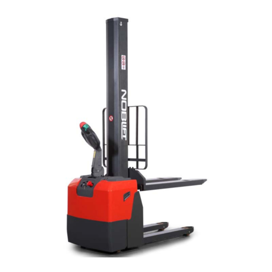
- Page 1 NOBLELIFT EQUIPMENT Service & Maintenance Manual PS10M Electric Pallet Truck V-PS10M-01.00 Date: 2013-11-20...
-
Page 2: Table Of Contents
CONTENTS FOREWORD .............................. 2 GENERAL ............................3 1.1 INTRODUCTION – MAINTENANCE SAFETY PRECAUTIONS ..........3 1.2 MEASUREMENT CONVERSIONS ....................7 SPECIFICATIONS ..........................11 2.1 LOCATION OF COMPONENTS ....................11 2.2 SPECIFICATION SHEETS ......................12 2.3 LUBRICATION ........................... 14 ELECTRICAL SYSTEM ........................15 3.1 ELECTRICAL DIAGRAM ...................... -
Page 3: Foreword
FOREWORD Proper operation, maintenance, troubleshooting and repairs are necessary to preserve the performance of the pallet truck over along period of time and ensure that fault and breakdowns do not occur. The object of this service manual is to provide the information necessary especially in connection with the performance of inspections and repairs mainly in the maintenance areas. -
Page 4: General
1. GENERAL 1.1 INTRODUCTION – MAINTENANCE SAFETY PRECAUTIONS Careless performing of the easy work may cause injuries. Take care to always perform work safely, at least observing the following. It is of utmost importance that maintenance personnel pay strict attention to these warnings and precautions to avoid possible injury to themselves or others, or damage to the equipment. - Page 5 Keep the flammable things away from the machine. Do not smoke in the working site. Battery should always be disconnected during replacement of electrical components. Always use the grades of grease and oil recommended by NOBLELIFT choose the viscosity specified for the ambient temperature.
- Page 6 Exhaust gas is dangerous provide ventilation when working in a closed space. Avoid breathing dust that may be generated when handling components containing asbestos fibers. Wear a gas mask if necessary. When working on top of the machine, be careful not to lose your balance and fall.
- Page 7 When changing the oil or fitter, check the drained oil and filter for any signs of excessive metal particles or other foreign materials. Always use NOBLELIFT genuine parts for replacement. ENSURE REPLACEMENT PARTS OR COMPONENTS ARE IDENTICAL OR EQUIVALENT TO ORIGINAL PARTS OR COMPONENTS. ...
-
Page 8: Measurement Conversions
1.2 MEASUREMENT CONVERSIONS Length Unit mile 0.01 0.00001 0.3937 0.03281 0.01094 0.000006 0.001 39.37 3.2808 1.0936 0.00062 100000 1000 39370.7 3280.8 1093.6 0.62137 2.54 0.0254 0.000025 0.08333 0.02777 0.000015 30.48 0.3048 0.000304 0.3333 0.000189 91.44 0.9144 0.000914 0.000568 mile 160930 1609.3 1.6093 63360... - Page 9 Pressure Unit kgf/cm Pa=N/m lbf/in lbf/ft kgf/cm 0.98067 98066.5 98.0665 14.2233 2048.16 1.01972 100000 14.5037 2088.6 Pa=N/m 0.00001 0.00001 0.001 0.00015 0.02086 0.01020 0.01 1000 0.14504 20.886 lbf/in 0.07032 0.0689 6894.76 6.89476 lbf/ft 0.00047 0.00047 47.88028 0.04788 0.00694 kgf/cm =735.56 Torr(mmHg)=0.96784atm Standard torque The following charts give the standard torque specification of bolts and nuts.
- Page 10 INCH TABLE 4T, 5T Classification Bolt type Bolt size Torque kgf · m (lbf · ft) Torque kgf · m (lbf · ft) 0.6 ± 0.06 1.7 ± 0.2 5/16 1.2 ± 0.12 3.0 ± 0.3 2.0 ± 0.20 5.6 ± 0.5 7/16 3.2 ±...
- Page 11 APPROXIMATE CONVERSIONS Conv Non–SI Conv Unit Factor Unit Factor Unit Torque × 8.9 × 0.113 newton meter (N·m) = ln·in = N·m × 0.74 × 1.36 newton meter (N·m) = lb·ft. = N·m × 0.102 × 7.22 newton meter (N·m) = kg·m = lb·ft.* Pressure (Pa = N/m...
-
Page 12: Specifications
2. SPECIFICATIONS 2.1 LOCATION OF COMPONENTS Main cover Emergency button Instruments cover Load backrest Tray 11. Forks Tiller 12. Load wheels Safety (belly) button 13. Hydraulic cylinder Accelerator (butterfly button) 14. Castors Discharge indicator and charging indicating LED 15. Drive wheel Key switch 16. -
Page 13: Specification Sheets
2.2 SPECIFICATION SHEETS Type sheet for industrial truck acc. to VDI 2198 Manufacturer`s type designation PS 10M PS 10M ST Power (battery ,diesel, petrol, gas, manual) Battery Battery Operator type Pedestrian Pedestrian Load Capacity / rated load Q(t) Load centre distance c(mm) Load distance ,centre of drive axle to fork x(mm) -
Page 15: Lubrication
2.3 LUBRICATION Hydraulic oil Hydraulic oil must have anti-wear qualities at least. It is not advisable to mix oils of different brands or types, as they may not contain the same required additives or be of comparable viscosities. Name: Thickened hydraulic oil. ISO Viscosity Grade Characteristics unit... -
Page 16: Electrical System
3. ELECTRICAL SYSTEM 3.1 ELECTRICAL DIAGRAM WIRING DIAGRAM FU1 : 10 A FU2 : 0,5 A FU01 : 150 A FU02 : 80 A... -
Page 17: Drive Wheel
3.2 DRIVE WHEEL Type: 3EL-DC-0.75 Drive Motor Model HS XQT-0.75-1DH1U Rate voltage DC 24V R.P.M 3200rpm Rate output 1.0kw Rate hour 60 min. Rated current 45 A Rated Exciting current 6.4A Min Exciting current 3.5A Insulation class F class Electromagnetic Brake Model G027-REB0908X-R Rate voltage... - Page 18 100% DURATION OF DISCHARGING LIFE TEST CURVE ( ENVIRONMENTAL TEMPERATURE = CHARGING CURVE...
-
Page 19: Charger
3.5 CHARGER Type: QQE192-8CH17-26A MAIN PRODUCT SPECIFICATION Output current Max. output power battery capacity Input voltage Output voltage range 240W 40AH-100AH 230Vac +28.2Vdc ENVIRONMENTAL CONDITION Item Technical specification Unit Remark Humidity 5%-95% With package ≦3000 Altitude Work normally Cooling Natural convection cooling Working under full load ELECTRICAL CHARACTERISTICS Input characteristics... - Page 20 Protection characteristics Item Technical requirements Unit Remark Output over voltage Lockout protection The charger software limits the maximum output Software over voltage voltage to a level suitable for the connected battery protection system When the internal temperature rises to 85℃,it turns into pulse charge mode.
- Page 21 LED TERMINATOR DIAGRAM & DEFINITION FAN TERMINATOR DIAGRAM&DEFINITION RELAY TERMINATOR DIAGRAM & DEFINITION...
-
Page 22: Curtis Controller
3.6 CURTIS CONTROLLER CURTIS 1311 HANDHELD PROGRAMMER The Curtis 1311 handheld programmer provides programming, diagnostic, and test capabilities for the controller. The power for operating the programmer is supplied by the host controller via a 4-pin Molex connector. The programmer includes a 7-line alphanumeric LCD display, rockertype keys for navigating through the display and for modifying parameters (+/-), and three keys that can be used as bookmarks. - Page 23 back through the menu structure. To set a bookmark, press one of the bookmark keys for about three seconds, until the Bookmark Set screen is displayed. To jump to a set bookmark location, quickly press the appropriate bookmark key (1, 2, or 3). Note that the bookmarks are not permanently stored in the programmer.
- Page 24 Max Speed Arm open Wakier 4200 5000 Max Speed Arm open Standon 5000 4200 Max Speed Turtle Max Speed 5000 2100 Interlock brake decel rate Mast high Mode Seconds Mast low Mode Seconds Steer Angle Speed Reduction Max Speed 4201 6000 Steer Angle...
- Page 25 Current Pot input Lift Pot Min 4095 Lift Pot Max 4050 4095 Lower Pot Min 4095 Lower Pot Max 4050 4095 Delay set Pump Lift Seconds Delay Delay PD closed Seconds after Pump lift Delay Lower Seconds after lift Control Mode Select 0 - Speed...
- Page 26 Low Accel Rate Seconds Neutral Decel Rate Seconds Neutral Decel Rate Seconds Full Brake Rate HS Seconds Full Brake Rate LS Seconds Low Brake Rate Seconds Fine Tuning Partial Decel Seconds Rate HS (High Speed) LS (Low Speed) Reversal Soften Max Speed Accel 1 Seconds Speed...
- Page 27 Restraint Restraint Forward Restraint Back Soft Stop Speed Position Hold Position Hold Enable Set Speed Settling 3013 5000 Time Set Speed Threshold Entry Rate Exit Rollback Reduction Current Limits Drive Current Limit Regen Current Limit Brake Current Limit Current Limit Interlock Brake Current Limit...
- Page 28 Forward Volt Deadband Forward Map Forward Max Volt Forward Offset Reverse Volt Deadband Reverse Map Reverse Max Volt Reverse Offset Throttle Filter HPD SRO Type Sequencing Seconds Delay Throttle Enable Brake Brake Pedal Enable Brake Type Brake Deadband Volt Brake Map Brake Max Volt Brake Offset...
- Page 29 Torque Preload Seconds Cancel Delay EM Brake Fault Motor Revs Drivers Main Contactor Main Enable Pull In Voltage Holding Voltage Battery Voltage Compensated Interlock Type Open Delay Seconds Weld Check Enable Main Check Enable Main DNC Runtime Volt Threshold Precharge Enable Proportional Driver PD Enable...
- Page 30 External Supply Min mAmper PWM Frequency 100 1000 Motor Typical 500 8000 4000 Speed Swap Encoder Direction Swap Phases Encoder Steps Encoder Options Encoder Solution Encoder Fault Setup Fault Detection Enable Encoder Pulse Fault Seconds Detect Time Fault Stall Time Seconds LOS Upon Encoder Fault...
- Page 31 Cell Full Volts 2.04 Volt Cell Empty Volts Per Volt 1.73 Cell Discharge Time Minutes Reset Percent Dual Drive Dual Motor Enable Dual Motor Slave Node Other LOS Max Speed 100 8000 Master Steer Angle (deg) Turn Accel Rate Seconds Critical Angle (deg) Max Turn Speed Inner Wheel Speed...
- Page 32 Distance 1 Capture 1320 Distance 2 Capture 1320 Distance 3 Emergenc y Reverse EMR Enable EMR Type Interlock EMR Time Limit Seconds EMR Speed 1000 6000 EMR Accel Rate Seconds EMR Decel Rate Seconds Interlock Braking Enable Decel Rate HS Seconds Decel Rate LS Seconds...
-
Page 33: Battery Indicator
Tests Test Enable Test Throttle Motor Poles Max Test Speed 1000 500 3000 Max Test Current SlipGain 3.85 Field Weakening Control FW Base Speed 1550 200 6000 Field Weakening Weakening Rate Min Field Current Ampere Motor Type Reset Controller 3.7 BATTERY INDICATOR Type: CURTIS 803RB2448BCJ3010 Front View Rear View... - Page 34 Monitoring of the battery continues when Pin 2 is turned off and the display is not lit. The hour meter display is unaffected by Pin 2, although it cannot accumulate more time as long as the keyswitch pin is not energized. The control inputs HRM (+) and HRM (–) are enabled by the keyswitch. Pin 2 is connected to the vehicle’s keyswitch.
-
Page 35: Replacing The Electrical Parts
OCR = Open Circuit Reset: If the gage is disconnected from the battery during recharge, the gage will retain the last indication. It will advance to full when reconnected only if the battery voltage is above the OCR level. For standard (“B”) reset, OCR = 2.09 VPC (VPC = volts per cell.) TROUBLESHOOTING Problem Possible Causes... - Page 36 STEP 2: remove 2 screws fixing the power line STEP 3: Remove 4 screws fixing the charger with with 2.5mm Allen wrench. opener. STEP 4: Remove the ground lead with 5mm Allen wrench, then you can replace the charger. REMOVING OF THE BATTERY STEP 1: Unplug the power line, light line, self-preservation line and connectors of light line, then remove 4 csrews fixing the charger base and remove it.
- Page 37 STEP 2: Press two springs of the battery cable tie, loosen it. STEP 3: Take out the hook. STEP 4: Remove the bolts fixing +/- pole with 10mm wrench.
- Page 38 REPLACING OF THE BATTERY INDICOTOR STEP 1: Remove the fixing screws with 6mm Allen wrench. STEP 2: Unplug the connector of the indicator, remove 2 screws then you can remove it. Instruction : ① Blank ②、③ positive pole input through the key switch ④...
- Page 39 REPLACING OF THE KEY SWITCH STEP 1: Remove the nut widdershins. STEP 2: Unplug the connectors fixing the cable 3- , 5-, then you can remove the key switch. REPLACING OF THE EMERGENCY BUTTON STEP 1: Remove 2 screws fixing the emergency button with wrench. Avoid losing the screws! STEP 2: Remove 4 screws with 6mm Allen wrench.
- Page 40 STEP 3: Remove 2 screws fixing emergency STEP 4: Dismantle the black plug with hand on button with 3mm Allen wrench. the emergency button. STEP 5: Remove B+ cable of the emergency button with 14mm wrench, then you can remove REPLACING OF THE FUSE ANG CONTACTOR STEP 1: Open the protective cap of the fuse STEP 2: Remove the screws of the contactor with...
- Page 41 STEP 3: Remove the fixing screws of the contactor with wrench then you can remove it. REPLACING OF THE CONTROLLER STEP 1: Unplug the connectors, remove screws fixing +/- pole and 3 wiring harness (U, V, W) with 5mm Allen wrench.
- Page 42 STEP 2: Remove 4 screws fixing the controller with 5mm Allen wrench. There is some thermal Silicone Grease on the back of the controller! REPLACING OF THE MAGNET SWITCH STEP 1: Unplug the connectors fixing the truck body. STEP 1: Remove 2 screws fixing the magnet switch.
-
Page 43: Tool For Repairing The Pin Of Electrical Plug
3.9 TOOL FOR REPAIRING THE PIN OF ELECTRICAL PLUG Application Figure Tool for removal of pins / sleeves. Tool for application of pins / sleeves Tool for release of lock Tool for application of secondary locking 2 – pole Tool for application of secondary locking 4 – pole Tool for removal of pins / sleeves... -
Page 44: Control Handle
4. CONTROL HANDLE No. Part name No. Part name Bushing, 23/19*17*10 Air spring Handle mounting bracket Handle cable Shaft, φ17 Micro switch Z-15GW2 Roll pin, φ4x24 Screw, M4x25 Socket hex bolts M8x25 Cover Elastic washer 8 Screw, M4x10 Socket hexa bolts M8X16 Tillerarm... -
Page 45: Replacing Of The Control Handle
No. Part name No. Part name Butterfly left or throttle switch left Seesaw-left or toggle button left Button for horn Magnet holder for seesaw Spring Hinge spring Bearing for camshaft Contact base Magnet Belly switch cover Spring for belly botton switch Optional cover Socket hexagonal Screw, M6X10 Seesaw right or toggle button right... - Page 46 STEP 4: Remove the driving switch axle. STEP 5: Remove the screws fixing the PCB board unplug the connectors and then you can replace the PCB board. Don’t miss the shaft sleeve when removing the PCB board.
-
Page 47: Replacing Of The Interlock Switch
4.2 REPLACING OF THE INTERLOCK SWITCH Step 1: Remove 4 screws on back cover of Step 2: Dismantle 2 screws fixing SA from the left handle with Allen wrench. of the handle lever with Allen wrench. 4.3 REPLACING OF THE AIR SPRING STEP 1: Remove the upper screws fixing the air STEP 2: Remove the below screws fixing the air spring with 6mm Allen wrench. -
Page 48: Hydraulic System
5. HYDRAULIC SYSTEM 5.1 HYDRAULIC FLOW DIAGRAM INSPECTION OF HYDRAULIC OIL External appearance Smell Condition Countermeasure Fine Fine Clear and no discoloration Possible to use Inspect the viscosity and if fine Clear but the color becames bright Fine Mixed with other oil it can be continuously used Color changed like milk. -
Page 49: Replacing Of The Pump Station
5.3 REPLACING OF THE PUMP STATION STEP 1: After removing the handle, remove 4 STEP 2: Remove the pipe joint of the pump with screws of the cover, then take out it. 24mm wrench. STEP 3: Remove the cable FP fixing the contactor and cable E2 fixing the motor. -
Page 50: Replacing Of The Lowering Magnetic Valve
5.4 REPLACING OF THE LOWERING MAGNETIC VALVE STEP 2: Take out the magnetic valve, unplug the STEP 1: Remove the screws fixing the magnetic valve with 19mm wrench. connectors signed J1-2- and 13-2-, then you can replace the lowering magnetic valve. 5.5 REPLACING OF THE CONTACTOR OF THE PUMP STEP 1: Remove the screw fixing the cable on the STEP 2: Loosen the screw of the hoop with... -
Page 51: Replaciing Of The Cylinder
STEP 3: Remove the screws fixing the carbon STEP 4: Press the spring then the carbon brush brush. will pop-up by the spring. 5.7 REPLACIING OF THE CYLINDER STEP 1: Remove 6 screws fixing the cover of the STEP 2: Lower the forks to the bottom, remove cylinder. - Page 52 STEP 5: remove the circlip of the Sprocket wheel STEP 6: Remove the pin roll of the chain wheel. seat with circlip plier. STEP 7: Take out the chain wheel. STEP 8: Fix the chain wheel base, then remove the screws with 18mm wrench. STEP 9: Take out the chain wheel base.
-
Page 53: Drive Wheel
STEP 11: Remove screws fixing cylinder with STEP 12: Lift up the truck until it higher than 6mm wrench. cylinder. STEP 11: Pull up the cylinder and then you can replace it. 6. DRIVE WHEEL 6.1 REPLACING OF THE SENSOR Lift up the truck before operating! Take care of yourself! STEP 1: Remove 4 screws fixing the motor with 2.5mm wrench. -
Page 54: Replacing Of The Break
STEP 2: Tilt the sensor with screwdriver, then you can take out the sensor and replace it. 6.2 REPLACING OF THE BREAK Part name Part name Gaiter Spring Friction plate Carrier Body magnetic Screw Break disk Screw M5x45 Break anchor plate STEP 1: Remove 6 screws with 6mm Allen wrench, and then you can remove the break. -
Page 55: Replacing Of The Rim
STEP 2: Remove the break pad. 6.3 REPLACING OF THE RIM STEP 1: Remove 2 screws fixing the cable board STEP 2: Remove 10 screws fixing the rim with and 3 screws fixing the wiring harness (U, V, W) 5mm Allen wrench, then you can remove the rim with 3mm wrench and 10mm wrench, then unplug and replace it. -
Page 56: Caster Wheel
7. CASTER WHEEL 7.1 OPERATION OF THE CASTER WHEEL First, let the pallet truck to be slanting, then dismantle four screws. Note to help the nut when turning the screws. Then you can dismantle the caster and replace it. 7.2 ADJUSTING THE PRESSURE FOR THE DRIVE WHEEL After using some time, the drive wheel might wear off, the pressure for the drive wheel will not be enough, and drive wheel can not bit into the ground and slip. -
Page 57: Trouble Diagnostics
8. TROUBLE DIAGNOSTICS 8.1 REGULAR MAINTENANCE • Only qualified and trained personnel are allowed to do maintenance on this truck. • Before maintaining, remove the load from the forks and lower the forks to the lowest position. • If you need to lift the truck, follow chapter 4b by using designated lashing or jacking equipment. Before working, put safety devices (for instance designated lift jacks, wedges or wooden blocks) under the truck to protect against accidental lowering, movement or slipping. - Page 58 • 21 Check if correct fuses are used, if necessary replace. • 22 Test the audio warning signal • 23 Check the contactors • 24 Check the frame leakage (insulation test) • 25 Check function and wear of the accelerator •...
- Page 59 b. Lubricating points Lubricate the marked points according to the maintenance checklist. The required grease specification is: DIN 51825, standard grease. Bearings in wheels Main frame post Chain Hydraulic system Gear box c. Check and refill hydraulic oil The required hydraulic fluid- type is •...
-
Page 60: Trouble Shooting
8.2 TROUBLE SHOOTING Trouble shooting TROUBLE CAUSE REPAIR Load weight too high Lift only the max. capacity, mentioned on the ID-plate Battery discharged Charge the battery Lifting fuse faulty Check and eventually replace the Load can’t be lifted lifting fuse Hydraulic oil level too low Check and eventually refill hydraulic Oil leakage...
Need help?
Do you have a question about the PS10M and is the answer not in the manual?
Questions and answers