Advertisement
Quick Links
Advertisement

Related Manuals for Noblelift PSE22 SL


Summary of Contents for Noblelift PSE22 SL
- Page 1 CONTENT...
- Page 2 1.GENERAL 1.1 INTRODUCTION – MAINTENANCE SAFETY PRECAUTIONS 1.2 MEASUREMENT CONVERSIONS 2.SEPCIFICATION 2.1 O VERVIEW OF THE MAIN COMPONENTS 2.2 S EPCIFICATION 3. ELECTRICAL SYSTEM 3.1 E LECTRICAL CIRCUIT DIAGRAM 3.2 E LECTRICAL ASSEMBLY 3.3 M AIN CIRCUIT HARNESS 4. BATTERY (MAINTENANCE-FREE BATTERY) 5.
- Page 4 Foreword This specification briefly introduces the technical parameters of our pallet, the structure of the main components, working principle and operation, maintenance, maintenance and other requirements and contents. Please read this manual carefully before operation to ensure safe and effective material handling through proper driving and maintenance.
- Page 5 1.GENERAL 1.1 INTRODUCTION – MAINTENANCE SAFETY PRECAUTIONS Maintenance work may cause injuries. Always take care to perform work safe, least observing the following. It is of utmost importance that maintenance personnel pay strict attention to these warnings. and precautions to avoid possible injury to themselves, others or damage to the equipment.
- Page 6 ■ Battery should always be disconnected during replacement of electrical components. ■ Always use the grades of grease and oil recommended by NOBLELIFT choose the viscosity specified for the ambient temperature. ■ Exhaust gas is dangerous provide ventilation when working in a closed space.
- Page 7 When changing the oil or fitter, check the drained oil and filter for any signs of excessive metal particles or other foreign materials. ■ Always use NOBLELIFT genuine parts for replacement. ENSURE REPLACEMENT PARTS OR COMPONENTS ARE IDENTICAL OR EQUIVALENT TO ORIGINAL PARTS OR COMPONENTS. ■...
- Page 8 1.2 MEASUREMENT CONVERSIONS Length Unit mile 0.01 0.00001 0.3937 0.03281 0.01094 0.000006 0.001 39.37 3.2808 1.0936 0.00062 100000 1000 39370.7 3280.8 1093.6 0.62137 2.54 0.0254 0.000025 0.08333 0.02777 0.000015 30.48 0.3048 0.000304 0.3333 0.000189 91.44 0.9144 0.000914 0.000568 mile 160930 1609.3 1.6093 63360...
- Page 9 0.01020 0.01 1000 0.14504 20.886 lbf/in2 0.07032 0.0689 6894.76 6.89476 lbf/ft2 0.00047 0.00047 47.88028 0.04788 0.00694 kgf/cm2=735.56 Torr(mmHg)=0.96784atm Standard tightening torque The following charts give the standard tightening torques of bolts and nuts. Exceptions are given in sections of “Disassembly and Assembly” METER TABLE Classification 4T, 5T...
- Page 10 Classification Bolt type Bolt size Torque kgf · m (lbf · ft) Torque kgf · m (lbf · ft) 0.6 ± 0.06 1.7 ± 0.2 5/16 1.2 ± 0.12 3.0 ± 0.3 2.0 ± 0.20 5.6 ± 0.5 7/16 3.2 ± 0.32 8.9 ±...
- Page 11 1.1 ± 0.1 2.6 ± 0.2 4.6 ± 0.3 8.5 ± 0.4 19 ± 1.0 33 ± 2.0 TORQUE FOR SWIVEL NUT WITH O-RING Tube O.D (inch) Thread (in) Torque (kgf·m) UN 13/16 - 16 9.5 ± 0.95 UN 1 3/16 - 12 18 ±...
- Page 13 APPROXIMATE CONVERSIONS Conv Non–SI Conv Unit Factor Unit Factor Unit Torque Newton meter (N·m) × 8.9 = ln·in × 0.113 = N·m Newton meter (N·m) × 0.74 = lb·ft. × 1.36 = N·m Newton meter (N·m) × 0.102 = kg·m ×...
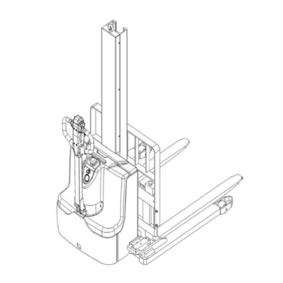
- Page 14 Application Remove pin Install pin Loose lock Two-hole lock Four-hole lock Remove pin 2.Sepcification 2.1 Overview of the main components...
- Page 15 Drive motor cover Accelerator (butterfly- switch) Balance wheel Multifunction tiller Drive wheel Electricity meter Hydraulic cylinder Chassis with mast Charging cable Main cover Load wheel Emergency button Charging indicating LED Key switch Protective screen Safety (belly) button 18 Forks...
- Page 16 PSE10M Bearing wheel 11. Accelerator (butterfly switch Fork arm 12. Multi-function handle Key switch 13. The front panel Electricity meter and charging indicator LED 14 Load Backrest lamp Emergency stop button Hydraulic oil cylinder Chassis and door frame 16. Drive motor housing Protective Cover 17.
- Page 17 2.2 Specification Technical data (PSE10SL) 1.Main technical data...
- Page 19 Technical data (PSE10MSL)
- Page 20 Technical data (PSE10M) Type sheet for industrial truck acc. to VDI 2198 General data Manufacturer`s type designation PSE10M...
- Page 21 Power (battery, diesel, petrol, gas, 电动 manual) Operator type 步行式 Load Capacity / rated load Q (t) Load center distance C (mm) Load distance, center of drive axle to X (mm) fork Wheelbase Y (mm) 1281 Weight Service weight Axle loading, laden front/rear 477/957 Axle loading, unladen front/rear 335/119...
- Page 23 3. Electrical system 3.1 Electrical circuit diagram 3.2 Electrical assembly Item description Qty. Note Shield (proximity switch) Hexagon socket head screws Spring washer Flat washer Electronic components battery Flat mat Hexagon socket head screws Battery holder Battery holding seat Fixed Angle Hexagon socket head screws Control wiring harness...
- Page 24 The fuse tube Limit switch short wiring The fixed frame LED fault display component Cross recessed pan head screws Connector mounting frame Charger holder A car fuse holder Plug-in type fuse Cross recessed pan head screws The fuse holder Cross recessed pan head screws Connector mounting frame Connector mounting frame Cross recessed pan head screws...
- Page 25 Cable -4B+-16-8-8-120 Cable -PB--16-6-8-950 Cable -B--6-6-6.3-810 Drive wheel harness assembly Cable -B+-2.5-6-8-1050 Copper platoon Cable -B--2.5-6-8-1130 4. Battery (maintenance-free battery) Charging of the battery The storage battery shall be charged with the original charger, and the operation shall be carried out strictly in accordance with the maintenance instruction.
- Page 26 optional: 2 battery of 12V/ 106Ah Maintenance of batteries the vehicle is powered by a maintenance-free battery and no maintenance is required for the battery during use 4.3 Battery test A. Battery status check Weak batteries can cause or cause problems with the controller and power circuits. Please make sure the battery is in good condition before troubleshooting other areas.
- Page 27 5. The charger 5.1 Overview This model adopts the built-in charger, the specification is 24V/10A Input voltage: 100~240V 50~60Hz Input current: 4.0A (maximum) Work efficiency: above 220V 90% Operation mode: single chip control on/off micro computer Output voltage: 24V Output current: 10A Applicable battery: 24V 50~120Ah lead-acid battery The ambient temperature and humidity: 0℃~40℃...
- Page 28 6.Controllor 6.1 Appearance Logic part plug-in: 14 cores Electromagnetic brake plug-in: 2 cores Programming port plug-in: 4 cores Power part plug-in: AMP plug-in Note: Switching the terminals of the controller M1 and M2 can change the running direction of the vehicle. Vehicle fault code reading A red LED light near the controller blinks quickly to represent the number of fault codes, and there is an interval between them.
- Page 29 2, electromagnetic brake drive open circuit BRAKE ON FAULT Brake opening fault 1. Open the electromagnetic brake coil 2. Electromagnetic brake drive short circuit CURRENTSENSE Current detection fault 1, motor or motor wiring short circuit FAULT 2. Controller failure EEPROM CHECKSUM EEPROM error EEPROM malfunction or failure FAULT...
- Page 30 4. It can be removed by removing the retaining bolt 5. Installation is the reverse process 7. Curtis handheld unit Note: Handheld unit attention function is for the convenience of vehicle inspection and maintenance, without the approval of the vehicle manufacturer, the controller parameters are not allowed to adjust, in order to avoid vehicle and personal safety accidents.
- Page 31 From the Curtis handheld unit menu list, find: Monitor... According to the need, open the corresponding detection menu sub-item, run the vehicle, observe the handheld value changes. Curtis handheld unit menu contents The Curtis 1313 handheld programmer is used to configure the Curtis electronic control system. Through this programmer, you can adjust and save set parameters, real-time monitoring of controller data and fault diagnosis The programmer has two interfaces, one is used to communicate with the electronic control, the other is used to communicate with the PC, the programmer has a battery box and a memory card.
- Page 32 Power up the programmer By inserting the connector of the hand-held programmer into the programming port of the controller, the hand-held programmer will automatically power up and display the control information on the controller.
- Page 33 The menu structure. The main menu consists of nine submenus, each of which is displayed with a specific icon, and each item in the submenu is arranged in a hierarchy. Some menus contain only one item of information, but most contain multiple items, and you can go to the next level of submenus by opening each item folder.
- Page 34 Troubleshooting menu In the main menu, Select the "Diagnostics" icon and press the function key corresponding to Select to enter the Fault diagnosis menu, which contains two folders: "Present Errors" and "Fault History." Note: Sometimes the fault caused by a temporary event caught in the circuit is not a system fault. It can be determined by rebooting the system and seeing if the fault disappears automatically.
- Page 36 8. Instruments 8.1 overview of electric meters The discharge pattern is represented by 10 LED display segments. The LED light on the far right lights up only when the battery is properly charged. As the battery's charge dropped, the LEDs turned on one at a time, but only one at a time. A second LED light to the left flashes, indicating "energy reserve"...
- Page 37 8.2 Replace the electric meter 1. Unscrew the two fixed nuts of the meter by hand 2. Remove metal ring 3. Replace the electric meter immediately 9. Driving wheel 9.1 Drive wheel overview...
- Page 38 Large drive assembly ARMA Drive Assembly See part manual for part name. On the electric side, drive motors turn their drive wheels, allowing the vehicle to move forward/backward. Controlled by a controller. The drive motor is connected to the controller via MI and M2 wires. The controller runs the drive motor based on input from multiple switches and sensors as well as internal parameter Settings.
- Page 39 9.3 Stator testing 1.Carefully wipe contaminants on the stator surface using a clean cloth dipped in alcohol Notes: Contaminants in the stator may cause damage to the coil and therefore to the stator itself. 2.Measurement of resistance per phase (uv,vw,wu) using multimeter Rated resistance:0.4Ω...
- Page 40 The battery is dirty, the electrolyte is on top of the The vehicle did not reach its maximum speed. battery. The current flows through the battery box, which applies voltage on the forklift frame: clean the battery with baking soda...
- Page 41 10. Hydraulic system 10.1 Overview 液压原理图 The hydraulic system operates other hydraulic parts through hydraulic force from pump. 1. The main hydraulic pump is driven by the pump motor controlled by the controller. 2. The main hydraulic pump uses the rotating force output from the motor to pressure the oil in the hydraulic tank and conveys the oil to the lifting cylinder.
- Page 42 the key switch is turned on. Upper limit switch closing handle rising switch closed pump contactor suction 10.2 Disassembly of pump motor 1. Disconnect pump motor B+ /B- terminal cable. 2. Disconnect hose from hydraulic pump. 3.Remove fixing bolt between pump motor and pump, then remove motor.
- Page 43 Installation torque:55±10n.m (40±7lb.ft). 4. Install pump motor in reverse order. 5. Add hydraulic oil to tank according to specifications given in manual.
- Page 44 10.3 Replace oil seal of lifting cylinder. 1. Remove the cylinder head with a crescent wrench 2.Remove piston, then remove retaining ring...
- Page 45 2. Remove dustproof seal and shield ring and Y-type seal 3. Remove o-seal and shield ring, then repair hose. Installation way is in reverse sequence...
- Page 46 10.4 Hydraulic motor fault Breakdown Reason Bad connection or fuse burning. Check the battery connection. Check the key fuse. Check if hydraulic pump motor is likely to cause fuse burning. The key switch or pump station contactor is not turned off.
- Page 47 Oil dirty Air leaks into the inlet line Low oil level oil channel limited Safety valve settings are too low Oil thin High temperature Air leakage in the system Pump wear is too high The system operates at too high a pressure. The safety valve is too high.
- Page 48 3: Down switch 4: Lifting switch 5: horn switch 2 Operation Instructions Emergency reverse switch: when the vehicle is running forward, the driver's body touches the button to make it close, the vehicle will run along the direction of the fork for 3 seconds, and then stop running. (Note: If the key is closed in advance before opening the key switch, the vehicle will not be able to operate) Acceleration knob switch: control the running direction and speed of the vehicle.
- Page 49 3. Open the handle cover 4. Unplug the connector (note the wire harness number) 5. Remove the entire switch 6. Unscrew the screw with a cross screwdriver...
- Page 50 7. The interlock switch can be replaced...
- Page 51 11.3 Replace the handle accelerator 5. Remove handle back cover screw and remove back 6. Unscrew the fixing screw of the accelerator with a cover cross screwdriver to replace it Regular maintenance • Only qualified and trained personnel can perform maintenance work on this vehicle •...
- Page 52 ∙ Check hydraulic oil level and recharge if necessary ∙ Add hydraulic oil after 12 months or 1500 hours of work ∙ Check and adjust the function of hydraulic valve (1600/2000/2500kg +0/+10%) Mechanical system ∙ Check if there is deformation and damaged on fork ∙...
- Page 53 ∙ Check Lift up and down ∙ Check proximity switch of tiller Summary ∙ Check label ∙ Check bearing wheel and adjust height, replace if worn out ∙ Test one more time Lubrication points Lubricate marked points according to maintenance list. Required grease specification: DIN 51825 standard grease. 1 load wheel bearing 2 the door frame 3 the chain...
- Page 54 Check fuse. Remove the main cover and the fuse is in the position shown below. Fuse specifications are shown below FU1 10A FU2 0.5A FU01 60A FU02 100A...
Need help?
Do you have a question about the PSE22 SL and is the answer not in the manual?
Questions and answers