Table of Contents
Advertisement
Quick Links
INSTRUCTION HANDBOOK
Electric Stackers
PSE12BD / PSE12ND
WARNING
Do not use the electric truck before reading
and understanding these operating
instructions.
NOTE:
• Please check the designation of your
present type at the last page of this
document as well as on the ID-plate.
• Keep for future reference.
Version 05/2021
PSE12BD/PSE12ND-SMS-003-EN
Advertisement
Table of Contents

Related Manuals for Noblelift PSE12BD


Summary of Contents for Noblelift PSE12BD
- Page 1 INSTRUCTION HANDBOOK Electric Stackers PSE12BD / PSE12ND WARNING Do not use the electric truck before reading and understanding these operating instructions. NOTE: • Please check the designation of your present type at the last page of this document as well as on the ID-plate.
- Page 2 FOREWARD Before operating the electric stacker, read this ORIGINAL INSTRUCTION HANDBOOK carefully and understand the usage of the truck completely. Improper operation of the truck may create a danger situation. This handbook describes the usage of different electric stackers. When operating and servicing the truck, make sure, that it applies to your type.
-
Page 3: Table Of Contents
TABLE OF CONTENTS CORRECT APPLICATION ........................3 DESCRIPTION OF THE STACKER ....................4 Overview of the main components ....................4 Main technical data ........................6 Description of the safety devices and warning labels (Europe and other, except USA) ..... 8 Identification plate ........................ - Page 4 1. CORRECT APPLICATION It is only allowed to use this electric stacker according to this instruction handbook. The trucks described in this handbook are self-propelled pedestrian controlled electric power stackers, with electrically powered lifting function. The trucks are designed for stacking operations in dedicated racking by lifting and lowering the palletized loads up to the desired lifting heights.
-
Page 5: Description Of The Stacker
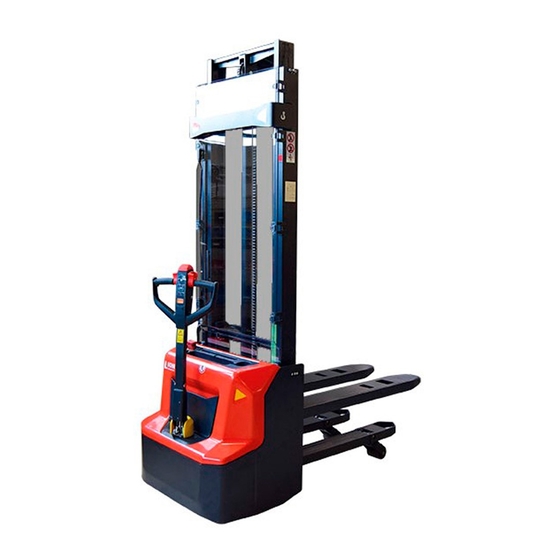
2. DESCRIPTION OF THE STACKER a. Overview of the main components Fig. 1: Overview main components Mast 10. Main cover 19. LCD Fork carriage 11. Cover 20. Emergency button Load roller assembly 12. Cover 21. Spring cord Chassis 13. Protective board 22. -
Page 6: Main Technical Data
b. Main technical data Fig. 2: Technical data... - Page 7 Table1: Main technical data for standard version Type sheet for industrial truck acc. to VDI 2198 PSE12BD PSE12ND Manufacturer`s type designation Battery Power (battery ,diesel, petrol, gas, manual) Operator type Pedestrian Load Capacity / rated load Load Capacity / rated load (mast lift)
-
Page 8: Description Of The Safety Devices And Warning Labels (Europe And Other, Except Usa)
5 / 10 Max. gradeability, laden/ unladen Electromagnetic 5.10 Service brake 0.65 Drive motor rating S2 60min Lift motor rating at S3 7.5% Battery acc. to DIN 43531/35/36 A, B, C, Battery voltage, nominal capacity K5 V/Ah 2 x 12 / 85 24 / 60 2 x 27 Battery weight... -
Page 9: Identification Plate
which switches the driving function away from the operator, if the truck travels towards the operator and the tiller is activated in the tillers operating zone. Follow also the instructions given on the decals. Replace the decals if they are damaged or missing. d. -
Page 10: Warnings, Residual Risk And Safety Instructions
3. WARNINGS, RESIDUAL RISK AND SAFETY INSTRUCTIONS DO NOT • Put foot or hand under or into the lifting mechanism. • Allow other person than the operator to stand in front of or behind the truck when it is moving or lifting/lowering. •... -
Page 11: Commissioning, Transporting, Decommissioning
4. COMMISSIONING, TRANSPORTING, DECOMMISSIONING a. Commissioning Table 2: Commissioning data Type PSE12BD/ 3600 PSE12ND/ 3600 Commissioning weight [kg] Dimensions 3600 3600 [mm] After receiving our new stacker or for re-commissioning you have to do following before (firstly) operating the truck: •... -
Page 12: Decommissioning
Transportation DURING TRANSPORTATION ON A LORRY OR TRUCK ALWAYS FASTEN THE TRUCK SECURELY Lower the forks and park the truck securely. Fasten the truck according to Fig. 6 by fixing dedicated lashing belts to chassis, Fork carriage and mast, and fasten the other side at the transporting truck. c. -
Page 13: Daily Inspection
5. DAILY INSPECTION This chapter describes pre-shift checks before putting the truck into operation. Daily inspection is effective to find the malfunction or fault on this truck. Check the truck on the following points before operation. Remove load from truck and lower the forks. DO NOT USE THE TRUCK IF ANY MALFUNCTION IS FOUND. -
Page 14: Operation Instructions
INCLINED SURFACES The truck is equipped with an electromagnetic failsafe stopping and parking brake. PSE12BD: Always lower the forks fully. Press the emergency switch (20). PSE12ND: Always lower the forks fully. Press the button, green LED ring is off (Fig.8), and press the emergency switch (20). -
Page 15: Residual Lift Diagram
b. Residual lift diagram The residual lift diagram indicates the maximum capacity Q [kg] for a given load centre c [mm] and the corresponding lift height H [mm] for the truck with horizontal load. The white markings on the mast indicate if the specific lifting limits reached. For instance (Fig.9. left) with a load centre of gravity distance c of 600 mm and a maximum lift height H of 3600 mm, the max. -
Page 16: Travelling
e. Travelling TRAVEL ON INCLINES ONLY WITH THE LOAD FACING UPHILL DO NOT TRAVEL ON INCLINES MORE THAN SPECIFIED WITH THE TECHNICAL DATA. TRAVELLING IS ONLY ALLOWED IF THE FORKS ARE LOWERED DOWN TO THE LIFTING POINT (<300MM). Fig.11: Operating direction After starting the truck by activation from Pin-code panel carefully move the tiller to the operating zone (‘F’, fig.11). -
Page 17: Steering
f. Steering ou steer the truck by moving the tiller to the left or right side. When travel in front direction (opposite to direction of forks) the turning of tiller bar to right side will cause the truck turning clockwise. g. -
Page 18: Pin-Code Panel
IP grade:IP65 Main functions For PSE12BD,it can be operated only when correct password is typed. For PSE12ND, it can be operated only when correct password is typed or valid ID card is used. There are two passwords of pin-code panel, one is the default user password 1234, and you can use it immediately. -
Page 19: Battery Charging And Replacement
PSE12ND is equipped with the following lithium battery: 24V / 60Ah, 19kg IT IS ONLY ALLOWED TO USE LEAD ACID BATTERY FOR PSE12BD. IT IS ONLY ALLOWED TO USE LITHIUM BATTERY FOR PSE12ND. PLEASE CONSIDER THE MAXIMUM OPERATING TEMPERATURE OF THE BATTERIES. -
Page 20: Matters Requiring Attention (Lithium Battery)
Installation environment In order to ensure the best operating performance, the battery need to be kept under normal working conditions: between 0 and 40 degrees Celsius and normal humidity. Avoid excessive temperature difference on both sides of the battery (more than 5℃) Emergency management Below are examples of several ways to deal with possible emergencies: •... -
Page 21: Replacement
Thirdly, unloosen and remove the battery fixing frame. For PSE12BD, remove the second battery on bottom following the same way of disassembly of the first battery. The installation is in the reverse order. -
Page 22: Charging
It is normally off, when it appears (fixed) it shows activation of the “soft” mode of the truck, in which maximum speed and acceleration are reduced. Monkey Wrench Symbol: It is normally off, when it appears (fixed) it shows the request of programmed maintenance or the alarm state. -
Page 23: Regular Maintenance
9. REGULAR MAINTENANCE • Only qualified and trained personnel are allowed to do maintenance on this truck. • Before maintaining, remove the load and lower the forks to the lowest position. • If you need to lift the truck, follow chapter 4 b by using designated lashing or jacking equipment. -
Page 24: Lubricating Points
• Check if correct fuses are used, if necessary replace. • Test the audio warning signal • Check the contactors • Check the frame leakage (insulation test) • Check function and wear of the accelerator • Check the electrical system of the drive motor b. -
Page 25: Checking Electrical Fuses
d. Checking electrical fuses Fig. 15: Location of fuses Table 5: Size of the fuses Rate FU01 150A FU02 FU2 (PSE12ND) 1.5A e. Removing, reattaching guarding DO NOT USE THIS TRUCK, IF THE GUARDING IS DAMAGED OR NOT CORRECTLY ASSEMBLED! If the guarding needs to be removed - de-attach holding clamps carefully. -
Page 26: Trouble Shooting
TROUBLE SHOOTING • If the truck has malfunctions follow the instructions, mentioned in chapter 6. Table 6: Trouble shooting TROUBLE CAUSE REPAIR Lift only the max. capacity, Load weight too high mentioned on the ID-plate Battery discharged Charge the battery Check and eventually replace Lifting fuse faulty the lifting fuse... - Page 27 Stop using and cool down the Electric system overheated truck Check and if necessary replace Defective heat sensor the heat sensor The controller is damaged. Replace the controller. The stacker starts up The accelerator not moves back to Repair or replace the suddenly its neutral position.
-
Page 28: Wiring/ Circuit Diagram
11. WIRING/ CIRCUIT DIAGRAM Electrical circuit diagram FU1 : 60 A FU1 : 10 A FU2 : 150 A FU2 : 6 A FU01 : 10 A FU01 : 150 A FU02 : 60 A Fig. 16: Electrical diagram manual steering PSE12BD... - Page 29 FU1 : 10 A FU2 : 6 A FU3 : 1.5 A FU01 : 150 A FU02 : 60 A Fig. 17: Electrical diagram manual steering PSE12ND...
-
Page 30: Hydraulic Circuit
Table 7: Description of electrical diagram Code Item Code Item Code Item Auxiliary Height detection Contactor module switch 3 Tiller Pump motor DC power switch Fork height limit Controller Driving motor micro switch 1 Mast height limit FU01 Fuse 150A Inter-lock switch micro switch 2 FU02... -
Page 31: Declaration Of Conformity (Valid, If Sold Within The Eu)
CE-DD-002 12. DECLARATION OF CONFORMITY (valid, if sold within the EU) [GB] CE Declaration of Conformity The signatory hereby declares that the specified machine conforms to the EU Directive 2006/42/EC (Machine Directive) and 2014/30/EU (Electro- Magnetic Compatibility, EMC) including their amendments as translated into national legislation of the member countries. The signatory is individually authorized to compile the technical documents. - Page 32 nacionālajai likumdošanai. Parakstu īpašnieki ir atsevišķi pilnvaroti sastādīt tehniskās dokumentācijas. [N] EU-KONFORMITETSERKLÆRING Undertegnede bekrefter hermed at de enkelte betegnede maskin med kraftdrift tilsvarer de europeiske retningslinjene 2006/42/EC (maskinretningslinje) og 2014/30/EU (elektromagnetisk fordraglighet - EMV) inklusiv disses endringer og den tilsvarende rettsforordning til omsetning av nasjonal rett. Hver undertegnede er fullmektig til å...
Need help?
Do you have a question about the PSE12BD and is the answer not in the manual?
Questions and answers