Lorex L20WD800 Series Instruction Manual
20” wide screen lcd monitor with built-in digital video recorder
Hide thumbs
Also See for L20WD800 Series:
- Quick start manual (12 pages) ,
- Frequently asked questions manual (24 pages) ,
- Network setup manual (23 pages)

Related Manuals for Lorex L20WD800 Series


Summary of Contents for Lorex L20WD800 Series
-
Page 1: Digital Video Recorder
20” WIDE SCREEN LCD MONITOR WITH BUILT-IN DIGITAL VIDEO RECORDER Instruction Manual English Version 2.0 MODEL: L20WD800 Series www.lorexcctv.com © Copyright 2008 LOREX Technology Inc. - Page 2 Thank you for purchasing the LCD / 8 Channel DVR Combo. Lorex is committed to providing our customers with a high quality, reliable security product. This system offers a whole new level of security surveillance to the consumer market. Combining the...
-
Page 3: Important Safeguards
Important Safeguards Important Safeguards In addition to the careful attention devoted to quality standards in the manufacture process of your video product, safety is a major factor in the design of every instrument. However, safety is your responsibility too. This sheet lists important information that will help to assure your enjoyment and proper use of the video product and accessory equipment. - Page 4 Important Safeguards Service 12. Servicing - Do not attempt to service this video 18. Cleaning - Unplug the video product from the wall equipment yourself as opening or removing covers outlet before cleaning. Do not use liquid cleaners or may expose you to dangerous voltage or other aerosol cleaners.
-
Page 5: General Precautions
4. Keep enough space around the unit for ventilation. Slots and openings in the storage cabinet should not be blocked 5. During lightning storms, or when the unit is not used for a long time, disconnect the power supply, antenna, and cables to protect the unit from electrical surge LOREX TECHNOLOGY INC. http://www.lorexcctv.com... - Page 6 LCD/DVR COMBO FEATURES LCD/DVR COMBO FEATURES Monitor • 20.1” Wide screen LCD with user selectable aspect ratio (Wide 16:9, Standard 4:3) • Professional Grade High Resolution (1680x1050) Glossy LCD panel • VGA Input - use your LCD Display as a PC monitor •...
-
Page 7: Table Of Contents
Table of Contents Table of Contents Getting Started ..................9 Tips & Tricks - Useful System Information ..........10 System Loading Sequence ......................12 Monitor Display Shutoff ......................12 System Shutoff .......................... 12 Front Panel ..................13~14 Rear Panel ..................15~16 Side Panel - USB Ports ...................... - Page 8 Monitor - Menu Settings ............71~74 Appendicies System Specifications - Appendix #1 .................. 75~76 Lorex Client 4.0 Software Requirements - Appendix #2 ............77 Setting up Remote Viewing - Appendix #3 ................78~90 Using the Auto Email Feature - Appendix #4 ..............91~94 Recommended Tips for System Setup - Appendix #5 ............
-
Page 9: Getting Started
Getting Started Getting Started The system comes with the following components: POWER ADAPTER LCD MONITOR & DVR COMBO UNIT MOUSE CLEANING CLOTH MANUALS, QUICK START GUIDE & SOFTWARE CD REMOTE CONTROL ETHERNET CABLE * HARD DRIVE SIZE AND CAMERAS VARY BY SPECIFIC MODEL. PLEASE REFER TO YOUR PACKAGE FOR CONTENT DETAILS. -
Page 10: Tips & Tricks - Useful System Information
Tips & Tricks - Useful System Information Tips & Tricks - Useful System Information The following Tips & Tricks contain useful information about your System: • Your default System Password is 1234. This password may be required when entering menus, reviewing Recorded Data, Archiving, PTZ, and for Remote Access. - Page 11 Tips & Tricks - Useful System Information Basic System Setup The following connections are recommended prior to loading the System for the first time.
-
Page 12: System Loading Sequence
Tips & Tricks - Useful System Information System Startup / Shutdown System Loading Sequence • Press the POWER button located on the front panel of the System to start the unit, or press the Power Button on the Remote Control. •... -
Page 13: Front Panel
Front Panel Front Panel 1. System Power Button 2. Multi-Function Modes 3. Setup Menu 4. Return Button 5. Navigation & Enter 6. Power LED 6. Recording LED 8. Network Connection LED 1. SYSTEM POWER BUTTON - Press the System Power button to turn the Monitor display ON/ OFF. - Page 14 Front Panel Front Panel 1. System Power Button 2. Multi-Function Modes 3. Setup Menu 4. Return Button 5. Navigation & Enter 6. Power LED 6. Recording LED 8. Network Connection LED 4. RETURN BUTTON - Exits a menu and returns the screen to the default view for the selected Mode.
-
Page 15: Rear Panel
Rear Panel Rear Panel 10 11 1. DIN Video Inputs 2. BNC Video Inputs 3. VGA IN Port 4. Component Video IN 5. Component Audio IN 6. Relay / PTZ / RS-232 7. Ethernet 8. Power (DC 12V) 9. Audio Inputs 10. -
Page 16: Side Panel - Usb Ports
Rear Panel Rear Panel 10 11 1. DIN Video Inputs 2. BNC Video Inputs 3. VGA IN Port 4. Component Video IN 5. Component Audio IN 6. Relay / PTZ / RS-232 7. Ethernet 8. Power (DC 12V) 9. Audio Inputs 10. -
Page 17: Camera Installation
Camera Installation Camera Installation Before you install the camera, carefully plan where and how you will position the camera, and where you will route the cable that connects the camera to the System. Installation Warnings: • Select a location for the camera that provides a clear view of the area you want to monitor, which is free from dust, and is not in line-of-sight to a strong light source or direct sunlight. -
Page 18: Connecting Din Cameras
Camera Installation Connecting DIN Cameras 1. Connect the female end of the supplied DIN extension cable to the camera. NOTE: Confirm that the arrows on the DIN Camera Cable and the DIN Extension cable are pointed together when connecting the cable. If the pins in the DIN Cable are bent, the Camera will NOT function. -
Page 19: Connecting Bnc Cameras
Camera Installation Connecting BNC Cameras 1. Connect the Extension cable to the Camera and System: A. Connect the Barrel Power connector to a power adaptor. B. Connect the BNC connector to an available BNC Port of the System. C. Connect the Male Power connector to the Camera. D. -
Page 20: Multi-Function Display - Monitor Modes
Multi-Function Display - Monitor Modes Multi-Function Display - Monitor Modes This system contains a multi-function display, which allows the system to function in several modes: • Mode 1: DVR Mode - Displays the DVR with live camera view. • Mode 2: VGA Mode - Displays the device connected to the VGA Port on the monitor (i.e. -
Page 21: Dvr Mode (Mode 1)
Digital Video Recorder (DVR) Mode (Mode 1) Digital Video Recorder (DVR) Mode (Mode 1) DVR Mode is the primary mode for the System, and is the displayed when the system is powered on. In DVR Mode, the system performs the following functions: •... -
Page 22: Dvr Mode - Remote Control Usage
DVR Mode - Remote Control Usage DVR Mode - Remote Control Usage 1. MODE: Press the Mode Button to display the Multi-Function Mode Menu. 2. POWER: Press the Power Button to turn off the Monitor Display. Press and hold the button for 3 seconds to shut down the entire system. -
Page 23: Front Panel & Mouse Navigation Controls
Front Panel Navigation Controls Front Panel Navigation Controls This System has been designed to use the Mouse or Remote Control as the primary modes of navigation and configuration for the system. The Front Panel buttons can also be used to access the menus and configure the system. -
Page 24: On-Screen Display Menu
On-Screen Display Menu On-Screen Display Menu The On-Screen Display Menu is accessed by either: • Pressing the Up or Down Arrows on the Front Panel • Right Clicking the Mouse The Menu options include: 1. CHANNELS: Select a Channel Number (1~8) to display a camera in Full Screen Mode. -
Page 25: System Display
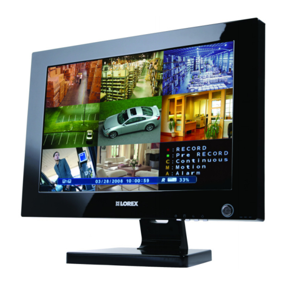
System Display System Display Camera Title: The Recording Status: title for the camera : Record is displayed in the upper left corner of : Pre Record the channel window, to a maximum of 11 C: Continuous characters. To M: Motion change the name, use the System A: Alarm... -
Page 26: Camera Display Modes
System Display Camera Display Modes Cameras can be displayed in several different modes by pressing the Display Button on the Remote Control or Mouse Menu. A Display Selection window will appear onscreen. Select from the available display types: Single Channel Quad (4) Channel 6 Channel Split View 8 Channel Split View... - Page 27 System Display PIP Mode (Reverse PIP) When using the PIP function when viewing in DVR MODE, it is referred to as ‘Reverse PIP’ (as normal PIP means displaying the DVR Screen as a PIP on any other mode). Select the PIP Button to display the VGA or Component mode in a PIP window.
-
Page 28: Menu Navigation Controls & Tips
Menu Navigation Controls & Tips Menu Navigation Controls & Tips YOUR SYSTEM PASSWORD IS: 1234 Virtual Keyboard Control The Virtual Keyboard control becomes available when keyboard input is needed for entering information such as Names, Network Information, etc. • Includes a~z, A~Z, 0~9 and Symbols.@#$%^&*() •... -
Page 29: System Setup Controls
System Setup Controls System Setup Controls • Enter the MENU screen by pressing the Main Menu SETUP button on the Remote Control, by pressing the SYSTEM MENU button on the Front Panel or by selecting DISPLAY - Setup of display options. SETUP from the Mouse Menu. -
Page 30: Display Menu
Display Menu OSD (Onscreen Display) Display Menu • Status Bar - Turns the status bar ON/ The Display Menu controls: OFF. The status bar displays: Recording State (Recording: Red, Pre-recording: Green) Network Indicators Time and Date % HDD Free Refer to Recording Settings on page 50). •... - Page 31 Display Menu MONITOR SEQUENCE • Sequence Dwell - Sets the cycle time Sets the Sequence Mode for the display of when the system is in Sequence Mode available channels. The Sequence Settings (between 1~60 seconds). for camera views can only be changed using the Mouse or Remote Control.
- Page 32 Display Menu Once the New Sequence has been created, the Sequence Setup Mode screens appear. These screens will set the sequence patterns (see the following for details). Modifying a Sequence • An existing Sequence can be Modified by selecting it from the list, and pressing ENTER.
- Page 33 Display Menu 5. Press the RETURN button when 2. Select the Display Mode by single left complete. and select SAVE & EXIT. clicking to switch (5 different Display Options - Single, Quad, 6-split, 8-split & 8-quad). 6. Press the SEQUENCE button on the Remote or Mouse Menu to switch to Sequence display.
- Page 34 Display Menu • Check or Uncheck the selected Cameras to have the video sent to a Secondary Monitor in Sequence. NOTE: Any cameras NOT selected will not be sent as video to the Spot Out Monitor. SCREENSAVER 5. Right click an empty spot outside of the squares when complete.
-
Page 35: Camera Menu
Camera Menu Camera Menu CAMERA TITLE • Covert - Turns the onscreen display of The Camera Settings and Controls: the Camera ON/OFF. Covert Cameras continue to record, however the camera CAMERA TITLE - Settings for the onscreen is not displayed onscreen. This feature display of individual Camera Titles. -
Page 36: Color Setup
Camera Menu COLOR SETUP PTZ SETUP Displays the settings for Brightness, PTZ Setup is for PTZ Type Cameras ONLY, Contrast, Tint and Color for individual which are not included with this system. For cameras. more information on PTZ Cameras, visit us on the web at http://www.lorexcctv.com. -
Page 37: Motion Sensor
Camera Menu PTZ PROPERTIES MOTION SENSOR • Sensitivity - Controls the Motion Sensitivity for the individual camera between 1 (low) ~ 10 (high). • Area Setup - Opens the Area Setup for the camera: Selected Areas are shaded in BLUE. •... -
Page 38: Sound Menu
Sound Menu Sound Menu SOUND • Live Audio - Turns Live System Audio The System Sound settings: (from the Audio on the terminal) to ON/ OFF. AUDIO - Settings for the system Audio for Live and Remote monitoring. • Audio Monitoring Channel - Select the channel for Listen-in Audio (Channels BUZZER - Settings for System Buzzer 1~4 ONLY). -
Page 39: System Menu
System Menu System Menu DATE/TIME • Date/Time - Sets the current system The System Setting controls contain: Date and Time.* DATE/TIME - Date and Time controls for the • Date Format - Sets the Date Display system. format (MM-DD-YYYY, YYYY-MM-DD, etc.). -
Page 40: Mail Setup
IP Address with every connection. MAIL SETUP Navigate to the DDNS website to configure the free account. Enter your The Mail Setup can use either the Lorex Mail specific information (as provided at the DDNS Site) Server or your existing Email settings to... -
Page 41: Mail Setup
Up to 7 new users can be added to the system. A maximum of 4 users can be NOTE: You must sign up for the Lorex remotely connected to the System DDNS to use the Lorex Mail Server. -
Page 42: System Management
System Menu SYSTEM MANAGEMENT System Information Screen • IP Address - Displays the IP address assigned to the System. • MAC Address - Displays the unique • System Information - Navigate to the MAC address assigned to the unit. This PRESS button, and choose ENTER to address is hard coded to the unit and display the System Information. - Page 43 This is useful if you are in a remote location, • Press OK to begin the update process. or if you would like to upgrade multiple units at different locations. Please refer to the Lorex Client Software manual for details on performing a Remote Firmware Upgrade.
-
Page 44: Control Device
System Menu Factory Defaults If the device is not detected, a message will indicate that No storage device was The System can be returned to the Factory found. default settings: • Select the ‘Factory Defaults’ option by selecting the PRESS button. •... -
Page 45: Event / Sensor
Event / Sensor Event / Sensor HDD EVENT • Smart Alarm - Sets the Smart Alarm ON/ The Event Sensor Setting controls contain: OFF. An alarm occurs when errors are detected with the drive. • Check Interval - Sets the Hard Drive check interval (1~24 hrs). -
Page 46: Buzzer Out
Event / Sensor BUZZER OUT ALARM OUT Sends an Alarm Out signal to a device (such Generates a Buzzer when an alarm is as a Manual Door or independent Light/ detected. Buzzer Alarm) when an Alarm In event is detected •... -
Page 47: Disk Management
Disk Management Disk Management EMAIL NOTIFICATION Sends an email to the specified users when the following events occur: • Notification - Sets the E-Mail notification ON/OFF. • HDD Event - A notification is sent if a Hard Drive event is detected (set to ON/ OFF). - Page 48 Disk Management • Format - Erases all Hard Drive data: Press start button. A warning message will be displayed with the prompt ‘All Recorded Data will be erased.’ Select OK to erase the data, or CANCEL to return without erasing the Hard Drive. •...
-
Page 49: Recording Menu Controls
Recording Menu Controls Recording Menu Controls • Enter the RECORDING MENU screen Simple and Advanced Modes Pressing the SETUP button on the This System allows you to configure the Remote Control Recording Options in two ways: Pressing the SETUP button on the front panel, or •... -
Page 50: Simple Recording Mode
Simple Recording Mode Simple Recording Mode Once the settings have been changed, a status window will appear indicating that the changes have been saved. Choose the OK Recording Operation button to close the status window and return to the Main Menu. The Recording Operation Menu allows the user to switch between Simple and Advanced Modes. -
Page 51: Advanced Recording
Simple Recording Mode Simple Recording Mode Advanced Recording Select a single or multiple time blocks: Recording Operation • Mouse Control: Click a single block to The Recording Operation Menu allows the open the Recording Type Menu. Click user to switch between Simple and and Drag a block of times to configure Advanced Modes, set the Recording multiple channels and times at once. - Page 52 Advanced Recording Advanced Recording Continuous / Motion Parameter Select an Hour (highlighted in ORANGE), and press ENTER again to open the Continuous / Motion Setup Camera Settings for the selected hour, or The Continuous/Motion Setup section select multiple blocks in a row and press controls the Recording settings for each ENTER.
- Page 53 Advanced Recording Continuous / Motion Schedule Select from: Sets the Time or Motion recording for each • NONE: Recording is turned OFF. channel (by hour). Select single or multiple • CONTINUOUS: Recording is always time blocks: • MOTION: Only starts the recording if motion is detected in the selected time interval.
-
Page 54: Alarm Setup Mode
Advanced Recording Advanced Recording Alarm Parameter Select an Hour (highlighted in ORANGE), and press ENTER again to open the Alarm Setup Mode Camera Settings for the selected hour, or The Alarm Setup section controls the select multiple blocks in a row and press Recording settings for each camera ENTER. - Page 55 Advanced Recording Alarm Schedule Once the settings have been adjusted for Sets the Alarm Recording for each channel the hour(s), the changed time block(s) will (by hour). Select single or multiple time be shown based on the legend: blocks: Legend: •...
-
Page 56: Archiving
Archiving Archiving Archiving Options The Archive feature copies data from the Hard Drive to a USB backup media (such as a Memory Stick or USB Hard Drive), optical drive (CD-RW / DVD-RW) or FTP.‘ NOTE: Make sure that you have removed all data from the USB device prior to backup. -
Page 57: Error Messages
Archiving Archiving Options Once the Start Time, End Time and Channel Selections have been completed, select the START Button A Drive Usage report will be displayed including Amount of space (in MB) needed, Start and End Times for Each Channel, with The Erasing status window displays size of recordings (in MB) and Size of the the completion state of the Erasing of... -
Page 58: Archive Backup To Ftp
Archiving Archive Backup to FTP • Port: Enter the Port used to connect to the FTP Site. A schedule for data backup to a local or Press the FTP Test button to test the remote FTP can be configured on the connection to the FTP site. -
Page 59: Search
Search Search • Press and Hold the arrow keys to select the Time (increments of 1 minute). Pressing the button without holding will Search mode allows you to locate previously increment 15 minutes. recorded video by Date and Time, or by Event Type. -
Page 60: Search By Event
Search Search By Event Searches the system based on Event Type (Alarm, Motion, Continuous or System). • Press the right arrow button on the front panel or remote control to access the Search By Event screen. • Select From and To dates, Events (Alarm, Continuous, Motion and Other) and Cameras •... -
Page 61: Vga Mode (Mode 2)
VGA Mode (Mode 2) VGA Mode (Mode 2) VGA Mode is used to display a device (i.e. a Computer) connected to the VGA Port on the monitor. To view a Computer using the Monitor: 1. Connect the PC to the Monitor using a VGA Cable. -
Page 62: Vga Mode - Remote Control Usage
VGA Mode - Remote Control Usage VGA Mode - Remote Control Usage Listed below is a quick reference for the Remote Control usage in VGA Mode. 1. MODE: Press the Mode Button to display the Multi-Function Mode Menu. 2. POWER: Press the Power Button to turn off the Monitor Display. -
Page 63: Component Mode (Mode 3)
Component Mode (Mode 3) Component Mode (Mode 3) Component Mode is used to display a device connected to the Component green, blue, and red inputs (Y/Pb/Pr) in high resolution (i.e. DVD Player, Set Top Box or Satellite Receiver). The Audio from the Component Device is connected to the Red and White audio inputs located to the right of the Component inputs. -
Page 64: Component Mode - Remote Control Usage
Component Mode - Remote Control Usage Component Mode - Remote Control Usage Listed below is a quick reference for the Remote Control usage in Component Mode. 1. MODE: Press the Mode Button to display the Multi-Function Mode Menu. 2. POWER: Press the Power Button to turn off the Monitor Display. -
Page 65: Picture Frame Mode (Mode 4)
Picture Frame Mode (Mode 4) Picture Frame Mode (Mode 4) Picture Frame Mode is used to display JPG images located on a USB Thumbstick (connected to a USB Port on the side of the monitor). To view a JPG Images using Picture Frame Mode: 1. -
Page 66: Picture Frame Mode - Remote Control Usage
Picture Frame Mode - Remote Control Usage Picture Frame Display Images will be displayed in Picture Frame Mode (based on the Menu settings). NOTE: Press the PIP button to display the DVR in the bot- tom right corner. Picture Frame Mode - Remote Control Usage Listed below is a quick reference for the Remote Control usage in Picture Frame Mode. -
Page 67: Picture Frame - Menu
Picture Frame - Menu Picture Frame - Menu NOTE: To display the Picture Frame menu, press the MENU Button on the front panel of the System or on the Remote Control. Insert the USB Thumbstick into the USB Port on the monitor prior to starting Picture Frame Mode. - Page 68 Picture Frame - Menu Picture Resizing Application 4. Select a location, and click on the Open button. An application has been included on the Software CD to resize your JPG images to 1600x1200 (highest recommended size), and save them directly to the USB Thumbstick.
-
Page 69: Installation Guide Mode (Mode 5)
Installation Guide Mode (Mode 5) Installation Guide Mode (Mode 5) The Installation Guide Mode is used to display the Installation Video included on the System drive. To view the Installation Video using the Monitor, press the Multi Function Mode button on the front of the Monitor, or press the Mode button on the Remote Control and selecting Installation Guide. -
Page 70: Installation Guide Mode - Remote Control Usage
Installation Guide Mode - Remote Control Usage Installation Guide Mode - Remote Control Usage Listed below is a quick reference for the Remote Control usage in Installation Guide Mode. 1. MODE: Press the Mode Button to display the Multi-Function Mode Menu. 2. -
Page 71: Monitor - Menu Settings
Monitor - Menu Settings Color Submenu Monitor - Menu Settings Press the Setup key on the remote control, or front panel of the System to enter the Monitor Setup Menu (when in VGA or Component Modes). The Monitor Setup Menu controls the behavior and look of the Monitor (i.e. -
Page 72: Display Settings
Monitor - Menu Settings Display Settings • Display Image: Sets the image display to Auto or Manual. • Aspect Ratio: Set the Aspect Ratio for the monitor. • Display Position: Adjust the Horizontal and Vertical screen positioning. Use the Arrow keys on the Front Panel or Re- mote Control to select from Auto Configura- tion, Phase, Clock or Highlight Window. - Page 73 Monitor - Menu Settings PIP Color Controls Submenu PIP Settings Use the Up, Down, Left and Right arrows to adjust the settings for Brightness, Contrast, Hue and Saturation. Press the Enter button to set, and the Return button to exit the menu.
- Page 74 Monitor - Menu Settings Misc. Settings • OSD Position: Determines the position of the Onscreen Display window. Use the Up, Down, Left and Right arrows to adjust the location of the screen. Press the Enter button to set, and the Return button to exit the menu Use the Arrow keys on the Front Panel or Re- mote Control to access the OSD Configura-...
-
Page 75: System Specifications - Appendix #1
X 7.4” / 532mm X 433mm X 188mm (Including Stand) • Environmentally friendly, recyclable packaging material As our products are subject to continuous improvement, LOREX Technology Inc. and its subsidiaries reserve the right to modify product design, specifications and prices, without notice and without incurring any obligation. -
Page 76: Dvr Specifications
System Specifications - Appendix #1 System Specifications - Appendix #1 DVR Specifications • 8 Channels with Pentaplex operation - View, Record, Playback, Back Up &Remotely Control the system simultaneously • MPEG4 Digital Video Compression - small file sizes without compromising video quality •... -
Page 77: Lorex Client 4.0 Software Requirements - Appendix #2
* Additional Hard Drive space required for recording. Recorded file size will vary depending on recording quality settings Please refer to the Lorex Client 4.0 Software User Guide included with your System for further details. Visit the Lorex support website at http://www.lorexcctv.com/support... -
Page 78: Setting Up Remote Viewing - Appendix #3
What do you need? • The LCD/DVR System. • A PC with the installed with the Lorex Client 4.0 software (refer to the Software Guide for installation instructions) • A Router (not provided with the system) and High Speed Cable or DSL Internet Connectivity... -
Page 79: Network Checklist
Setting up Remote Viewing - Appendix #3 Network Checklist The following checklist is provided to assist you in confirming that all steps have been successfully performed during Network Setup. Use this checklist in conjunction with the steps outlined on the following pages. 1. - Page 80 • Select the Network Menu. • Select the DDNS Server option, and use your information to complete the DDNS Configuration: DDNS Server Name: Lorex (default) Domain Name: Enter the name you set for the DDNS web configuration. User ID: Enter your user ID Password: Enter your password •...
- Page 81 Setting up Remote Viewing - Appendix #3 System - IP & MAC Address The IP & MAC Addresses are necessary for DDNS Setup (for remote access to IP Address the System). To Locate the System information, Press MAC Address the ENTER button on the Front Panel or Info on the Remote Control while viewing the Cameras.
- Page 82 Setting up Remote Viewing - Appendix #3 Network - Router Port Forwarding You will need to enable port forwarding on your Router to allow for external communications with your System for ports: • TCP/IP PORT 6100 • WEB PORT 80 Computers, Systems, and other devices inside your network can only communicate directly with each other within the internal network.
- Page 83 Network - Setting Up Your DDNS Account Lorex offers a free DDNS service for use with your System. A DDNS account allows you to set up a web site address that points back to your Local Network. The following outlines how to set up your free DNS account.
- Page 84 5. Click the Create New Account link at the bottom of the form to submit your request. 6. Your Account information will be sent to you at the E-mail Address you used in Step 3. DDNS Server Name: LOREX Domain Name: myurl...
- Page 85 Dear A, Thank you for activating your free Dynamic DNS account for your Lorex DVR Combo. Once you have set up your Lorex device and configured your network, you will be able to view your video images from anywhere in the world using the URL shown at the end of this message.
- Page 86 Setting up Remote Viewing - Appendix #3 2. Log into the Lorex DDNS Website at http://www.lorexddns.net and enter your Username and Password. Click the ACTION button located on the console to display a copy of the Configuration email:...
- Page 87 Once the DDNS settings have been configured online, the information must be entered on the System to allow for remote connection via the Lorex Client 4.0 Software (or through Internet Explorer): 1. Access the Main Menu Setup screens, and navigate to the SYSTEM option. Press the ENTER button to access the setup.
- Page 88 Setting up Remote Viewing - Appendix #3 Lorex Client 4.0 Software - Connection Manager The Connection Manager contains the setup information to allow the user to remotely connect to the System. Adding a Group Group - Right click on ‘Site’ to add a New Group.
- Page 89 Setting up Remote Viewing - Appendix #3 Adding a Site (Individual Unit Configuration) DVR Information - Enter the information specific to the unit (refer to page 30 for setup instructions): • Name - Enter a name for the unit. • IP / Domain Name - Enter the IP address or Domain Name for the System.
- Page 90 Setting up Remote Viewing - Appendix #3 Lorex Client 4.0 Software - Remote Connection Once the site setup profile has been created, a connection can then be made to the System: 1. Select the Site profile from the Dropdown List.
-
Page 91: Using The Auto Email Feature - Appendix #4
Outlook or any other mail program. There are two ways to configure these settings: • Configuration using the Lorex Mail Server. Make sure the box is checked, and you will not need to enter any additional information, however YOU WILL BE REQUIRED to set up your system on the Lorex web based DDNS at http://www.lorexddns.net... - Page 92 Using the Auto Email Feature - Appendix #4 This is an example of the same type of required settings (formatted for Microsoft Outlook). SERVER (Outgoing SMTP) PORT (More Settings, change only recommended your Internet Provider) USER & PASSWORD SECURITY NOTE: This example is not required for the System to function correctly. This is used to illustrate the required settings (using another program).
- Page 93 Using the Auto Email Feature - Appendix #4 System Menu - Mail Navigate to the System Menu, and select the Mail Option. New users can be added to the System through the User Management screen, and existing users can be edited. The important features in the User Setup are the E-Mail address and E-Mail Notification: •...
- Page 94 Using the Auto Email Feature - Appendix #4 Event / Sensor - E-Mail Notification Navigate to the System Menu, and select the Mail Option. • NOTIFICATION - Notification must be turned on for Automatic E-mail alerts to be sent. • HDD EVENT - Emails a notification to all active accounts when problems are detected with the Hard Drive.
-
Page 95: Recommended Tips For System Setup - Appendix #5
Recommended Tips for System Setup - Appendix #5 Recommended Tips for System Setup - Appendix #5 There are several tips outlined below that will assist you in setting up your system: Connecting and Mounting Cameras: 1. Connect the DIN Extension Cable to an open channel port on the back of the System. - Page 96 Recommended Tips for System Setup - Appendix #5 Navigating within the System Menu (cont.) Menu Navigation Controls This System has been designed to use the Mouse or Remote Control as the primary modes of navigation and configuration for the system. The Front Panel buttons can also be used to access the menus and configure the system.
- Page 97 Recommended Tips for System Setup - Appendix #5 Changing the Date and Time Setting the correct date and time for your system is important. Once the date and time have been set correctly, it is highly recommended that you format your Hard Drive.
-
Page 98: Formatting The Hard Drive
Recommended Tips for System Setup - Appendix #5 Formatting the Hard Drive Formatting the hard drive after changing the date, and before beginning the recording of YOUR data is recommended, as the system is set to Automatically start recording when powered on (continuous recording setting). -
Page 99: Camera Setup
Recommended Tips for System Setup - Appendix #5 Camera Setup Each camera should be assigned a name that corresponds to its use (i.e. Dock1, BackDoor, Cash3, etc.). This name is displayed onscreen, and helps to identify the camera location easily. 1. -
Page 100: Screen Saver Settings
Recommended Tips for System Setup - Appendix #5 Screen Saver Settings The screen saver will black the screen during a defined interval. 1. Enter MENU mode by pressing the MENU button on the front panel of the system, Remote Control or Mouse Menu. Select the SYSTEM SETUP Option. - Page 101 Recommended Tips for System Setup - Appendix #5 Backing up your System Configurations it is recommended to back up your system configurations to a Memory Stick. Configuring your system to meet your specific needs can be time consuming - having a backup of your settings will allow you to reset your unit with your personalized settings in the event of an unwanted change.
-
Page 102: Listen-In Audio - Appendix #6
Listen-in Audio - Appendix #6 Listen-in Audio - Appendix #6 There are 4 available DIN camera ports, 8 available BNC camera ports and 4 BNC Audio ports on the system - how many can be used for Listen-In audio, and how many can be used to record sound? How do I enable Listen-In Audio, and how do I set the Listen-in channel? -
Page 103: Playback Previously Recorded Data? - Appendix #7
Playback Previously Recorded Data? - Appendix #7 Playback Previously Recorded Data? - Appendix #7 Search mode allows you to locate previously recorded video by Date and Time, or by Event Type. • Press the Search Button on the front panel, Remote Control or mouse menu. Enter the User Name and Password (if required). - Page 104 Playback Previously Recorded Data? - Appendix #7 Search By Event Searches the system based on Event Type (Alarm, Motion, Continuous or System). • Press the right arrow button on the front panel or remote control to access the Search By Event screen. •...
-
Page 105: Setting Auto-Recording To Off - Appendix #8
Setting Auto-Recording to OFF - Appendix #8 Setting Auto-Recording to OFF - Appendix #8 The system is set to automatically start recording when powered on. You may wish to change these settings to better suit your security needs. These settings can be changed for an individual camera on one time block, or can be set for multiple cameras for multiple time blocks. - Page 106 Setting Auto-Recording to OFF - Appendix #8 Setting Multiple Time Blocks 1. Enter MENU mode by pressing the MENU button on the front panel of the system, remote control or mouse menu. Select the RECORD MENU Option. 2. Select the SIMPLE RECORDING MODE menu. Navigate using the up and down arrows on the front panel (or remote control).
-
Page 107: Setting Up Motion Recording - Appendix #9
Setting up Motion Recording - Appendix #9 Setting up Motion Recording - Appendix #9 The system is set to automatically start recording when powered on in Continuous Mode. You may wish to change these settings to better suit your security needs by having the cameras start recording when MOTION is detected. - Page 108 Setting up Motion Recording - Appendix #9 7. The Schedule Window will be displayed, with the Motion Time blocks displayed as highlighted boxes. 8. Press the Return Button several times to exit the Recording Menus. Remember to SAVE YOUR CHANGES! To check if the unit is recording in Motion, all channels should have a green box on the top right hand corner.
-
Page 109: Motion Area Setup
Setting up Motion Recording - Appendix #9 Motion Area Setup • Select the Motion Sensor Menu: Use the System menu to configure the Motion Detection areas. Setting the motion detection areas are useful to mask in specific areas (i.e. Doors or Windows), so when movement is detected in these areas the System Recording will begin. -
Page 110: Using The Storage Calculator - Appendix #10
Using the Storage Calculator - Appendix #10 Using the Storage Calculator - Appendix #10 The Storage Calculator application is used to calculate the amount of recording time available on your Hard Drive, based on the System Recording Settings. This application is located on the Software Installation CD (provided with your System) 1. -
Page 111: Hard Drive Replacement - Appendix #11
Hard Drive Replacement - Appendix #11 Hard Drive Replacement - Appendix #11 The System comes with a pre-installed Hard Drive, however the unit will work with a replacement single Hard Drive (up to 750GB). NOTE: Make sure that the System is OFF and the power cable has been disconnected before changing the Hard Drive. -
Page 112: New Hard Drive Format
Hard Drive Replacement - Appendix #11 New Hard Drive Format The New Hard Drive MUST be formatted. If a new HARD DRIVE is detected, the system will prompt you to FORMAT the drive. If you do not choose to format the HARD DRIVE, the drive will not be detected by the system. -
Page 113: Connecting A Spot-Out Monitor - Appendix #12
Connecting a Spot-Out Monitor - Appendix #12 Connecting a Spot-Out Monitor - Appendix #12 A connection to a Spot-Out Monitor (not included with the System) can be made through the SPOT OUT Port on the back of the System. • SPOT OUT - Displays Cameras in Sequence mode, regardless of the display on the DVR (i.e Camera Views, Menus, Playback, etc.) to a TV or VCR. -
Page 114: Connecting Motion / Alarm Device - Appendix #13
Connecting Motion / Alarm Device - Appendix #13 Connecting Motion / Alarm Device - Appendix #13 Motion detection and Alarm controls are enabled through the Menu system on the System. Additional motion sensor devices can be connected to the system (Motion Sensors, Door/ Window Sensors). -
Page 115: Connecting Ptz Cameras - Appendix #14
Connecting PTZ Cameras - Appendix #14 Connecting PTZ Cameras - Appendix #14 PTZ Cameras (not included with this system) can be connected to the PTZ Control Block on the back panel of the System. The PTZ Controls are enabled through the Menu system on the System. -
Page 116: Full Connectivity Diagram - Appendix #15
Full Connectivity Diagram - Appendix #15 Full Connectivity Diagram - Appendix #15 The following diagram outlines a general set of connections available with the System. PC for Remote Access ROUTER (Not Included) (Not Included) DVD PLAYER (Connect to VGA, Not Included) Not Included) SYSTEM SPEAKERS... -
Page 117: Optional Accessories
Optional Accessories Optional Accessories The following accessories are available to add to your existing system: TO ORDER THESE ITEMS, AND FOR A COMPLETE LISTING OF AVAILABLE PRODUCTS, PLEASE VISIT US ON THE WEB AT HTTP://WWW.LOREXCCTV.COM... - Page 118 It’s all on the web Product Information Specification Sheets User Manuals Software Upgrades Quick Start Guides Firmware Upgrades VISIT www.lorexcctv.com www.lorexcctv.com Lorex Technology Inc.
Need help?
Do you have a question about the L20WD800 Series and is the answer not in the manual?
Questions and answers