Lorex L21Q784 Instruction Manual
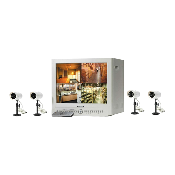
Ip enabled 21” 2 page / 8 channel color quad observation system with 4 night vision cameras
Hide thumbs
Also See for L21Q784:
- Network configuration manual (12 pages) ,
- Network setup manual (13 pages)
Table of Contents

Related Manuals for Lorex L21Q784


Summary of Contents for Lorex L21Q784
- Page 1 IP ENABLED 21” 2 PAGE / 8 CHANNEL COLOR QUAD OBSERVATION SYSTEM WITH 4 NIGHT VISION CAMERAS L21Q784 FOR MORE INFORMATION WWW.LOREXCCTV.COM BEFORE OPERATING THIS SYSTEM, PLEASE READ THIS MANUAL THOROUGHLY AND RETAIN IT FOR FUTURE REFERENCE...
- Page 2 IP Enabled 21” 2 Page/8 Channel Color Quad Observation System. LOREX is committed to providing our customers with a high quality, reliable security product that customers have come to expect from us. The IP enabled Observation system allows you to make an ethernet LAN connection from the monitor to a computer for internet monitoring.
- Page 3 • Increase the separation between the equipment and receiver. • Connect the equipment into an outlet on a circuit different from that to which the receiver is connected. • Consult the dealer or an experienced radio or television technician for help. Lorex Technology Inc. www.lorexcctv.com -ii-...
-
Page 4: General Precautions
GENERAL PRECAUTIONS: Read Instructions Servicing All of the safety and operating instructions should Do not attempt to service this product yourself as be read and understood before the product is used. opening or removing covers may expose you to Retain Instructions voltage or other hazards. -
Page 5: Table Of Contents
11. APPENDIX A – CONNECTING MONITOR TO A STANDARD VCR ------------------------------------------------------------------------------- 12. APPENDIX B - CONNECTING TO A SLAVE MONITOR ----------------------------- 13. APPENDIX C - CONNECTING TO A LOREX TIME LAPSE VCR FOR ALARM RECORDING ------------------------------------------------------------------- 14. CARE AND MAINTENANCE ------------------------------------------------------------------... -
Page 6: Cautions And Features
CAUTIONS: 1. All the warnings and instructions of this manual should be followed 2. Remove the plug from the outlet before cleaning. Do not use liquid aerosol detergents. Use water damped cloth for cleaning 3. Do not use this unit in very humid and wet places 4. -
Page 7: System
SYSTEM INCLUDES: 4- 1/4” CCD COLOR CAMERAS WITH 21” COLOR 2 PAGE/8 CHANNEL NIGHT VISION, METAL STAND AND QUAD MONITOR WITH REMOTE 57 FT CABLE CONTROL ALSO INCLUDES, IP SOFTWARE & LAN CABLE Please refer to the Quick Start Guide and CD for the Owner’s Manual (IP Server software) Note: This software must be installed... -
Page 8: Monitor Controls - Front Panel
MONITOR CONTROLS - FRONT PANEL: 1. Standby Switch - Pressing this switch will turn power OFF to the monitor. Pressing it again will turn the power ON. The master power switch, which controls the monitor is located at the back of the unit. Note: The monitor (Standby Switch) can be turned off while recording, provided the master switch is ON. - Page 9 9. Channel Freeze 3/7 - This button Freezes camera 3 or 7 when the monitor is set to full screen mode or in Quad mode. An “F” will appear in the On-Screen Display to indicate that the Freeze option is ON. 10.
- Page 10 4) To exit Zoom Mode, press the Zoom button once again. Note: the Zoom function is available in PIP/POP mode by holding the Zoom button for 3 seconds. b) Main - Another function of the Zoom/Main button that is used in PIP/POP mode. Refer to the PIP/POP section below for an explanation.
- Page 11 19. PIP Sequence – Pressing this button initiates Sequencing in Single PIP mode. Pressing this button a second time changes the channel of the fixed screen in PIP Sequencing. To exit PIP Sequencing, press the PIP/POP button. You can program whether the Main picture or the Sub picture switches during PIP Sequencing via the Menu.
-
Page 12: Main Menu Control
MAIN MENU CONTROL The Main Menu is pulled up by pressing the Menu button. Scroll up and down through the eight options by pressing the arrow keys. To enter a sub-menu, press the Menu button where the highlighted scroll bar is located. To exit the Main Menu, scroll down to the Exit option and press Menu. - Page 13 Alarm on a camera, change the setting to N.O (Normally Open). Note: some non-Lorex PIR motion sensors have a default setting of N.C (normally closed). In order to activate the alarm on such a PIR motion sensor, change the setting to N.C.
- Page 14 BLANK COLOR: Choose between blue, gray or black as the background screen color in Menu Mode. VCR OUT: When set to [ACTUAL], the system will output what is shown on the monitor to a VCR. When set to [QUAD], the VCR will record Quad mode, regardless of what’s appearing on the screen.
-
Page 15: Monitor Controls - Back Panel
MONITOR CONTROLS - BACK PANEL: 3 4 5 1. AC Input - This button is used to connect the supplied power cord from the monitor to an electrical outlet 2. Power - This button controls power to the entire unit . Depress the side with the ‘I’, to turn power ON. -
Page 16: Remote Control
REMOTE CONTROL: Features of the Remote Control. For more details on specific remote control features, refer to the Monitor features FUNCTION DESCRIPTION Cuts off the sound from the camera Turns Power to monitor ON/OFF Allows user to select individual cameras Quad 1/2 Sets monitor to Quad mode (P1/P2) FRZ 1/5... -
Page 17: Standard Wired Camera & Camera Installation
STANDARD WIRED CAMERA: Camera Lens – Delivers high quality image by using a 1/4” CCD Image Sensor LED’s - 6 Blue LED’s for day/night vision Speaker – Delivers sound from the monitor to the camera Camera Input – Connect cable to monitor Bracket –... -
Page 18: Monitor Connections & Trouble Shooting
MONITOR CONNECTIONS: 1. Camera 1 Input Connect one end of the supplied 65ft cable to the first wired camera, the other end to camera Input 1 2. Camera 2 – 8 Inputs Connect optional additional cameras to the camera 2-8 inputs using either the DIN or BNC camera inputs TROUBLE SHOOTING: If the system does not function properly, please check the following points. -
Page 19: Technical Specifications
TECHNICAL SPECIFICATIONS: MONITOR Picture Tube 21” Color Horizontal resolution 450 TV Lines Camera Capable Up to 8 Quad Speed 30 fps Camera Input 8 DIN / 8 BNC Alarm Inputs/Outputs 8 / 1 Input signal Composite 1 Vp-p, (V:0.714Vp-p, Sync:0.3Vp-p) Power Source Multi-voltage (AC100V –... -
Page 20: Optional Accessories
OPTIONAL ACCESSORIES The following accessories are available to add to your existing system. CABLE TIME LAPSE VCR NIGHTVISION Weatherproof Night vision Extends viewing length Used to record key events. accessory. Allows you to from Camera to monitor. Select From a 40 hour real see in the dark up to 35-40 Available In 65, 100 and time or 1280 Hour time lapse... -
Page 21: Appendix A - Connecting Monitor To Astandard Vcr
APPENDIX - A CONNECTING MONITOR TO A STANDARD VCR: PLEASE SEE THE DIAGRAM BELOW FOR CONNECTING YOUR VCR TO THE MONITOR. NOTE: Ensure the Standard VCR’s channel is set to A/V Mode in order to ensure reception. Consult your VCR’s Owners Manual to set the VCR to this setting. •... -
Page 22: Appendix B - Connecting To A Slave Monitor
APPENDIX - B CONNECTING TO A SLAVE MONITOR: Connections to another monitor (e.g. Slave Monitor) can be made through “MONITOR OUT” As show in the diagram below. -19-... -
Page 23: Appendix C - Connecting To A Lorex Time Lapse Vcr For Alarm Recording
APPENDIX - C CONNECTING TO A LOREX TIME LAPSE VCR FOR ALARM RECORDING: -20-... -
Page 24: Care And Maintenance
CARE AND MAINTENANCE: Please follow the following instructions to ensure proper care and maintenance of this system Keep your monitor and camera dry. If it gets wet, wipe it dry immediately. Use and store your unit in normal temperature environment. Extreme temperatures can shorten the life of the electronic devices.
Need help?
Do you have a question about the L21Q784 and is the answer not in the manual?
Questions and answers