Table of Contents
Advertisement
Quick Links
Download this manual
See also:
Instruction Manual
L23WD
View the System
Series
Demo on the System
Quick Setup Guide
with a press of a
button (10+)
PACKAGE CONTENTS:
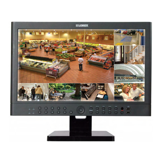
• 23" Widescreen LCD DVR
• Cameras & stands*
• HDD Pre-Installed*
• Camera extension cables*
• Mouse
• Ethernet cable
• Remote Control
• Software application CD
• Power Supply
• Quick Start Guide
• Owner's Manual
ATTENTION:
• * Number of Channels/ Screen Size/ Cameras/ Accessories/ Port configuration
and HDD (hard disk drive) capacity may vary by model. Check your package for
specific content information.
Exclusive Octaplex Operation
View
1
Public View
Record
8
2
Monitor
Entertainment
3
7
Playback
Display
6
4
PC Monitor
Backup
5
Remote Configuration
It's all on the Web
For detailed setup information, please
refer to your included User's Manual.
For additional information, please
visit our website
www.lorextechnology.com
* For setup of Instant Mobile Viewing
and MAC Compatibility refer to your
User Manual.
Information in this document is subject to change without notice. As our products are subject to
continuous improvement, Lorex Technology INC. and our subsidiaries reserve the right to modify
product design, specifications and prices, without notice and without incurring any obligation. E&OE ©
2010 LOREX. All rights reserved.
Time
BASIC SYSTEM SETUP
under 15 minutes
under 30 minutes
under 60 minutes
Time
Hand Tools
Hardware
BASIC INSTALLATION GUI DE
Router
under 15 minutes
under 30 minutes
under 60 minutes
over 60 minutes
Time: 20 Minutes
Hand Tools
Skills - Easy
STEP 1
Skill Level
Hand Tools
Hardware
Hi Speed
Router
easy
Intermediate
Connect DIN Cameras to the System:
Skill Level
1
* Connect cameras to extension
NOTE:
The arrow mark on top of
Connect one end of the Ethernet cable to an
cables by aligning the arrows.
the flat side of the camera and
Intermediate
advanced
easy
available port of your router (not included)
cable connectors should face
and the other end to the System's Network
outwards when connecting to the
Port.
system. This aligns cable pins from
being bent. If the pins are bent, the
camera will not function.
TIP:
Test the cameras prior to selecting a permanent mounting location by
Connect a USB mouse to the USB port
temporarily connecting the Cameras and Cables to your System.
on the front panel of the system.
Connect the first camera to the CH1 input.
Follow the same steps to connect the
additional cameras.
NOTE:
You cannot connect BNC and DIN
Connect one end of the power adaptor to the
cameras to the same channel
System and the other end to an electrical
simultaneously.
outlet. The power connector faces outward
and only goes in one way. Do not force.
TIP:
Tilt the System UP to locate the connection ports.
The DIN inputs are located in the center.
By default, the system does not require a password to login to the system.
OPTIONAL
TIP:
setup is complete.
1a
Connect BNC Cameras to the System:
The Virtual Keyboard
The system automatically opens the virtual keyboard
when you double-click a blank field, or when you
Male Power Connector - The male
Female Power Connector - The
need to enter system information.
power connector end of the Extension
female power connector (barrel) end
cable connects to the Camera.
of the Extension cable connects to the
To use the Virtual Keyboard:
Power Adaptor.
1. Click any desired letter, number, or character.
ATTENTION:
NOTE:
The ends of the extension cable are NOT the same - one end has
a Male power connector, and the other has a Female power connector. Before
permanently running the Camera Extension Cable, make sure that the cable
has been oriented between the Camera and the system correctly.
If you are using BNC cameras:
1. Click
1. Connect the extension cable to the camera.
2. Click SYSTEM SETUP. The MAIN window opens.
a. Connect the Male Power connector to the
3. Click SYSTEM.The SYSTEM window opens.
camera.
4. Under DATE TIME, manually select the date and
b. Connect the BNC connector to the
camera.
2. Connect the extension cable to the system.
NOTE:
a. Connect the BNC connector to an
Time Format.
available BNC port on the system.
5. Click APPLY and then click CLOSE to save your changes.
b. Connect the Female Barrel Power
connector to a power adaptor.
3. Connect the Power Adaptor to a wall outlet.
Time
BASIC SYSTEM SETUP
over 60 minutes
under 15 minutes
under 30 minutes
under 60 minutes
Time
Hi Speed
Hand Tools
Hardware
BASI C I NSTA L LATIO N GU IDE
Router
under 15 minutes
under 30 minutes
under 60 minutes
over 60 minutes
Time: 20 Minutes
Hand Tools
Skills - Easy
STEP 1
Skill Level
Hand Tools
Hardware
Hi Speed
CONTINUED
Router
advanced
easy
Intermediate
Connect the Ethernet Cable:
Skill Level
2
Intermediate
advanced
easy
Connect the Mouse:
3
Connect the Power Cable:
4
PRESS THE MONITOR POWER
BUTTON ON - LOCATED AT THE FRONT OF THE MONITOR.
NOTE:
Please wait until the system completes
loading. This may take up to 15 seconds.
User Name & Password
5
It is recommended to change the default password after the initial
To Log in
USER:
ADMIN
PASSWORD:
1234
Click "A" to shift between upper and lowercase letters.
Setting the Date & Time
6
in the status bar.
• The SETUP window opens.
time (yyyy/mm/dd; hh/mm/ss) and adjust using
NOTE:
It is highly recommended
the
buttons.
to set the time on the system
If desired, change the Date Format and the
prior to doing any recording.
TIP:
Under NETWORK TIME SERVER SETUP, click SYNC to synchronize
the system to the network time server (the system must be properly
connected to your network in order to use this function).
Time
NAVIGATION AND CONTROLS
over 60 minutes
under 15 minutes
under 30 minutes
under 60 minutes
over 60 minutes
Hi Speed
Hand Tools
Hardware
Hi Speed
BAS IC IN S TALL ATI ON GU IDE
Router
Time: 20 Minutes Skills - Easy
STEP 2
Skill Level
advanced
easy
Intermediate
advanced
Mouse
1
Left-Button: While navigating menus, click to select
a menu option. While in a split-screen display mode,
double-click an individual channel to view it in full-screen;
2
1
double-click again to return to the split-screen display
mode. Right-Button: Right-click anywhere on the screen
to open the Quick Menu.
Status Bar
2
The Status Bar (is always ON by default) gives you access to different
modes and functions of the system.
Main Menu
3
1. Click
in the Status Bar.
• The SETUP window opens.
2. Click SYSTEM SETUP.
Quick Menu
4
Right-click on any channel (in viewing mode
only) to open the Quick Menu. The Quick Menu
allows for quick access to key functions, including
quick playback, PIP, volume, and keylock. Click
anywhere outside the Quick Menu to exit.
Congratulations! You have completed STEP 1 & 2 successfully. Your system is now
ready to use. Refer to the owner's manual to learn how to record, search, playback,
and use other advanced features and all other features available with this system.
Logging into Web Remote Viewer (LOCALLY):
1. Press the RETURN button once on the
5. Click Install when the security
remote control or on the front panel of your
window opens.
system. Under the SYSTEM INFORMATION
6. Click the ActiveX toolbar when
screen you will find your system's IP
the main Web Remote Viewer
address.
window opens. Click Install
2. From your local computer, open Internet
ActiveX Control.
Explorer and type in the local IP address
7. Click Install when the security
and Port number (e.g. http://192.168.1.100).
window opens. The Web
A login window appears.
Remote Viewer automatically
detects and connects to your
http://your local IP address
system after the ActiveX
plug-in installs.
EXAMPLE
3. Enter in your System's user ID and
password. The Web Remote Viewer
window opens.
4. Click the Active X menu bar near the top of
the browser. Click Install ActiveX Control.
LOCAL LIVE SITE
Time
LOREX EASY CONNECT INTERNET
under 15 minutes
under 30 minutes
under 60 minutes
over 60 minutes
REMOTE VIEWING - BASIC
Hand Tools
Hardware
Hi Speed
REMOTE VIEWING INSTALLATION GUIDE
Router
STEP 3A
Hardware
Skills - Easy
Time: 20 Minutes
Time
- PC
Skill Level
ON YOUR PC
easy
Intermediate
advanced
under 15 minutes
under 30 minutes
under 60 minutes
over 60 minutes
Easy Connect Setup
1
Hand Tools
Hardware
Hi Speed
Router port forwarding is not required
Using your Internet Explorer web browser from
Router
your computer (Windows operating system only)
Skill Level
Go to
http://lorex.yoics.com
and
Detailed instructions
create an account.
available in the User Manual.
easy
Intermediate
advanced
For more advanced remote
monitoring refer to Step 3B.
NOTE:
There is no "www" in front of the address. The system must be
connected to your local network router for Yoics to automatically detect
the system.
2
A pop-up window opens and
informs you that your device
has been detected. Click
CONTINUE in the registration
screen to enable Yoics Easy
Connect.
You can rename your system
3
(e.g. myoffice). Click REGISTER
NOW. After the registration,
your system will be detected
automatically.
4
Your system now appears on
the left side bar under "My
Stuff"
NOTE:
This service is provided
free of charge. You do not have
to click the Upgrade Now
button to use the Remote
DVR Viewer
Viewer service.
Connect to your DVR
5
Click on the name of your device
under "My Stuff" on the left side
bar. Install ActiveX when Internet
Explorer prompts you.
DVR Viewer
Enter the System User Name
6
(ADMIN)
and Password
(1234)
and click OK to login
to the system.
Congratulations! Now that you have a Yoics account set up you can log in to
http://lorex.yoics.com to remotely view your cameras from anywhere in the world
using Internet Explorer web browser (Windows operating system only).
L23WD Series Quick Setup Guide - English - R1
Advertisement
Table of Contents

Related Manuals for Lorex L23WD Series


Summary of Contents for Lorex L23WD Series
- Page 1 Click Install ActiveX Control. the system to the network time server (the system must be properly continuous improvement, Lorex Technology INC. and our subsidiaries reserve the right to modify connected to your network in order to use this function).
- Page 2 DDNS domain from the confirmation email. For example, if 3. Click on NETWORK. and password. 4. Under IP, enter the IP address of your Lorex device as recorded your domain name is tomsmith.lorexddns.net, you only need 4. On RTSP SERVER PORT, click on AUTOPORT. Wait for a SUCCESS Create Account in Step 3B-1.
Need help?
Do you have a question about the L23WD Series and is the answer not in the manual?
Questions and answers