
Related Manuals for Holman 40485


Summary of Contents for Holman 40485
- Page 1 Installation Guide 40485 Holman Rancho Cordova, CA 95742 800-343-7486 InstallationSupport@holman.com 20240828R4 DATE: __________________...
-
Page 2: Table Of Contents
Before You Begin • Read all instructions carefully, and follow each step in proper sequence, for ease and speed in assembling your Holman product. • Be sure to put sealant around all threads entering cargo area to prevent water leaking into cargo area. -
Page 3: Parts List
Instructions – 40485 Parts List Hardware Kit For Technical Support Call: 800-343-7486, Monday-Friday, 7AM - 4 PM (PST) Page 2... - Page 4 Instructions – 40485 Hardware Kit (Cont.) For Technical Support Call: 800-343-7486, Monday-Friday, 7AM - 4 PM (PST) Page 3...
-
Page 5: Step 1 - Mounting Location
Instructions – 40485 Step 1 - Mounting Location • Ensure there is enough clearance for van slide without interfering with partition or other equipment. 19” • Position mount assembly in desired location in vehicle. Be sure to allow enough clearance in front of slide rails to close van side door. -
Page 6: Step 2 - Plus Nut Installation
Instructions – 40485 Step 2 - Plus Nut Installation DO NOT drill beyond depth of floor. Always check for wires, fuel tanks and lines, brake lines and other important vehicle functionality items prior to drilling and installing all products. • Drill hole using 25/64” drill bit and appropriate sized drill-bit stop collar. If 25/64” drill bit is not available, a 3/8”... -
Page 7: Step 3 - Mount Assembly Installation
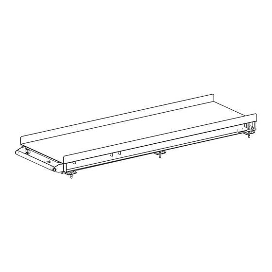
Instructions – 40485 Step 3 - Mount Assembly Installation • Using one 1/4” x 1” hex head bolt, one 1/4” lock washer, and one 1/4” fender washer at each mounting location, fasten the mount assembly to the vehicle floor. NOTE: If any of the mounting locations are over a floor channel depression, use a 1/4”... - Page 8 Instructions – 40485 • Be sure to center bearing assembly on mount assembly. • Lay top pan assembly on flat surface. • Using four 1/4” x 1/2” hex head bolts, four 1/4” lock washers, and four 1/4” flat washers, fasten handle brackets to top pan assembly in orientation shown.
-
Page 9: Use
Instructions – 40485 • Pull and hold latch handle forward. • While holding the latch handle forward on the top pan assembly, position the rear of the top pan assembly centered side to side over the mount assembly. • Push the top pan assembly back until it drops into place beyond the slide rails.
Need help?
Do you have a question about the 40485 and is the answer not in the manual?
Questions and answers