
Subscribe to Our Youtube Channel
Related Manuals for Holman 40475PE


Summary of Contents for Holman 40475PE
- Page 1 Instruction Guide 40475PE – 40475PL Holman Rancho Cordova, CA 95742 800-343-7486 InstallationSupport@holman.com 20240112R1 DATE: ________________...
-
Page 2: Table Of Contents
• Any previously installed flooring must be removed prior to installing Holman flooring. • Floor must be assembled in vehicle. • 40475HW hardware kit may be necessary to install some accessories to Holman flooring. (40475HW sold separately). • 40477P threshold kit must be installed when installing Holman flooring. (40477P sold separately). -
Page 3: 40475Pl & 40475Pe Parts List
Instructions – 40475PE, 40475PL 40475PL & 40475PE Parts List For Technical Support Call: 800-343-7486, Monday-Friday, 7AM - 4 PM (PST) Page 2... -
Page 4: 18-40475Pl Floor Hardware (All Floor Kits)
Instructions – 40475PE, 40475PL 18-40475PL Floor Hardware (ALL FLOOR KITS) For Technical Support Call: 800-343-7486, Monday-Friday, 7AM - 4 PM (PST) Page 3... -
Page 5: 18-40475Pe Floor Extension Hardware (40475Pe Only)
Instructions – 40475PE, 40475PL 18-40475PE Floor Extension Hardware (40475PE ONLY) Step 1 – Remove Factory D-Rings • Using T40 Torx bit, remove eight OEM D-Rings for ProMaster 159” wheelbase and ten OEM D-Rings for ProMaster 159” Extended wheelbase. Be sure to save D-Rings if re- installation is desired. -
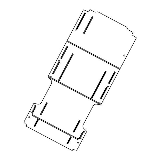
Page 6: Step 2 - Position Floor
Instructions – 40475PE, 40475PL Step 2 – Position Floor Floor must be assembled in vehicle. • Set front panel in position. • Press middle panel into aluminum extrusion of front panel. • Press rear panel into aluminum extrusion of middle panel. -
Page 7: Attaching Shelving To Floor
1-1/8” drill bit. • In the center of each hole, install a plus nut using the instructions below. • Use 1” x 3/8” plastic spacer (Holman p/n 40501) in each hole as needed to attach accessories to steel van floor. -
Page 8: Install Plus Nuts
Instructions – 40475PE, 40475PL Install Plus Nuts DO NOT drill beyond depth of floor or upper installation surface. Always check for wires, fuel tanks and lines, brake lines and other important vehicle functionality items prior to drilling and installing all products.
Need help?
Do you have a question about the 40475PE and is the answer not in the manual?
Questions and answers