Advertisement
Quick Links
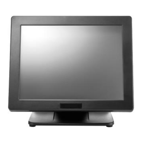
PS-3515/3516/3615/3616
Fanless Touch Terminal
User Manual
PS-3515
PS-3516
Package Contents
Fanless LCD touch terminal ...................................(x1)
Power adaptor..................................................(x1)
Power cord......................................................(x1)
User Manual....................................................(x1)
Recovery DVD................................................(x1)
(for pre-loaded OS model only)
※ The appearance of the product may be somewhat different from that of
the actual product, so the appearance of this product should be based
on that of physical products. The contents in this manual may be
updated at any time without prior notice.
13110904020 Ver. B0
PS-3615
PS-3616
1
Advertisement

Related Manuals for POSIFLEX PS-3616


Summary of Contents for POSIFLEX PS-3616
- Page 1 PS-3515/3516/3615/3616 Fanless Touch Terminal User Manual PS-3515 PS-3615 PS-3616 PS-3516 Package Contents Fanless LCD touch terminal ……………………………..(x1) Power adaptor…………………………………………..(x1) Power cord……………………………………………...(x1) User Manual…………………………………………….(x1) Recovery DVD…………………………………………(x1) (for pre-loaded OS model only) ※ The appearance of the product may be somewhat different from that of the actual product, so the appearance of this product should be based on that of physical products.
- Page 2 SOME IMPORTANT NOTES FCC NOTES This equipment has been tested and found to comply with the limits for a Class A digital device, pursuant to part 15 of the FCC Rules. These limits are designed to provide reasonable protection against harmful interference when the equipment is operated in a commercial environment.
- Page 3 種情況下,使用者會被要求採取某些適當的對策。 SAFETY INSTRUCTIONS This equipment is not suitable for use in locations where children are likely to be present. CONSIGNES DE SÉ CURITÉ Cet équipement ne convient pas à une utilisation dans des lieux pouvant accueillir des enfants. BATTERY CAUTION NOTES ...
- Page 4 Overviews of the PS-3515/3516/3615/3616 Front View Resistive Touch Panel LED Indicator Gen 7 Base PS-3515 PS-3516 P-CAP Touch Panel LED Indicator Gen 7 Base PS-3615 PS-3616 Rear I/O Cover Rear View Display Screw Hole Hinge for LCD Neck Cover Cable Cover Cable Exit...
- Page 5 Left Side View Right Side View Power Button Brightness Adjustment Button “+” Side Attachment Cover Brightness Adjustment Button “-” Bottom View Bottom I/O Cover View of I/O Interface Top I/O Ports COM4 Port USB 2.0 Port ※ The top I/O ports are provided for COM-based and USB-based peripheral devices, for example, customer display.
- Page 6 Bottom I/O Ports RJ45 LAN Port USB 2.0 Ports USB 3.0 Ports VGA Port COM Port (COM1/COM2/COM3) RJ11 Cash Drawer Port 12VDC-IN Power Jack Terminal from shipping mode to operation mode In consideration of proper packaging, before shipping, the terminal is folded, staying in shipping mode.
- Page 7 2. Overturn this terminal in the direction as indicated by the arrow in the right figure. 3. Place this terminal on a flat table. 4. Tilt this terminal to a degree in the direction as indicated by the arrow below. 5.
- Page 8 7. Push the cable cover back to the base. Terminal from operation mode to shipping mode To fold this terminal, refer to the following steps. Here, an equivalent model with GEN 7 base is taken below for example. 1. Remove the cable cover. 2.
- Page 9 4. Push the base-folding lever in the direction as indicated by the arrow below (1). Then, the display will be loosen and go down (2). 5. When the display goes down to a degree, loose the base-folding lever, as shown in the direction as indicated by the arrow below. 6.
- Page 10 Installing Optional Upgrade Kits and Peripherals PS-3515/3516/3615/3616 can work with multiple optional upgrade kits and peripheral devices, such as magnetic stripe reader (MSR), LCD monitor, cash drawer and the like. Before installing an optional upgrade kit and/or peripheral device, make sure that the system is powered off and the external power source is removed from the POS box to prevent electric hazard! Failure to follow the warning description will void the product warranty!
- Page 11 3. Push and tilt the terminal to the end in the direction as shown by the arrow. Then determine that the terminal is tilted to the end, as shown in the right figure. 4. Press the circled section with two thumbs and pull by force the two sides of the locking hook with two forefingers as indicated by the arrow.
- Page 12 7. Make the connector, which will be connected to the I/O port of the terminal, pass through the cable passage of base stand. 8. Push and tilt the terminal to the end in the direction as shown by the arrow. 9.
- Page 13 11. Cover the bottom I/O interface and gather the I/O cables to the circled cable arrangement area, as shown below. 12. Push and tilt the terminal to the end in the direction as shown by the arrow. 13. Arrange well the I/O cable located at the area of neck cover.
-
Page 14: Power Led Indicator
15. Shield the I/O cable exposure area with the cable cover. CAUTION: On doing insertion or extraction of a cable connector, please always hold the connector head itself instead of pulling the cable wire. Doing this could damage the cables and ports, which is considered as an artificial damage and is not covered by the warranty. - Page 15 Status Description Solid blue System power ON POWER Solid orange System standby Installing an Operating System This product is highly professional equipment. Therefore, we do NOT encourage you to install any operating system into this machine without professional assistance. We shall not be responsible for any technical support to questions on this aspect.
- Page 16 I/O & Expansion 4, 3 x DB9 on bottom I/O plate + 1 x RJ50 on top I/O Serial Port plate, 5V/12V support on all COM ports 5, 2 x USB3.0 + 2 x USB2.0 on bottom I/O plate + Standard USB Port 1 x USB2.0 on top I/O plate...
Need help?
Do you have a question about the PS-3616 and is the answer not in the manual?
Questions and answers