Table of Contents
Advertisement
Quick Links
Advertisement
Table of Contents

Related Manuals for Pyxis Guardian IK-2000 Series


Summary of Contents for Pyxis Guardian IK-2000 Series
- Page 1 Pyxis Lab Inc. June 4, 2024...
-
Page 2: Safety Information
Related Statements The manufacturer shall not be liable for direct, indirect, special, incidental or consequential damages resulting from any deficiency or omission in this manual. The manufacturer reserves the right to make changes to this manual and the products described in it at any time without notice or liability. Revised versions can be found on the manufacturer's website. -
Page 3: Table Of Contents
Analyzer Operation and Maintenance ....................43 10.3. Instrument Alarms and Descriptions ....................44 10.4. Replacing ST-765SS-SO3 pH, ORP and Sulfite Electrode Head ............45 10.5. Replacing ST-774 Dissolved Oxygen Cartridge Assembly (DCC-2)............46 10.6. Sensor Cleaning with Pyxis Probe Cleaning Kit ..................47... -
Page 4: Specifications
Specifications Item Guardian IK-2000 Guardian IK-2010 Guardian IK-2020 Guardian IK-2030 47522 47744 43809 48807 Guardian Boiler Feedwater Analyzer Level 1 Level 2 Level 3 Level 4 Dissolved Oxygen Measure Range 0.1 - 2,000 ppb / ±0.3ppb Optical - Blue Light Irradiated Excitation / Red Light Reference Dissolved Oxygen Method Red Light Reference Temperature Measure Range... -
Page 5: Product Description
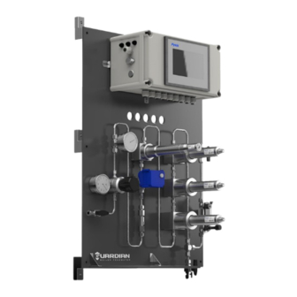
Guardian Boiler Feedwater Series was designed with the user in mind. The Guardian IK-2000 series boiler feedwater analyzer integrates up to four (4) unique Pyxis smart sensors. *NOTE* The base model will come equipped with one ST-774 sensor only and all remaining pre-plumbed stainless tee assemblies are plugged for future use as the user desires. -
Page 6: Sensor Description
The ST-774 offers an easily replaceable, front loading DO membrane cartridge (DCC-2) that has been independently developed by Pyxis Lab, with a typical service life of up to 2-years. This sensor is also well known in the industry for its ability to be Zero-Calibrated in the field using the Pyxis Sulfite-ZERO calibration kit and the connected display terminal. -
Page 7: Pyxis Guardian Hardware & Display Features
*NOTE* The Guardian Boiler Feedwater Analyzer panel design is identical for all 4 levels allowing users to purchase the base level 1 and later purchase and install as desired the additional Pyxis sensors without the need for equipment upgrade, configuration or... -
Page 8: Part Numbers & Ordering Details
(Ultra-Low Luminescent Dissolved Oxygen + Temp. Sensor 0.1-2,000ppb – Stainless Steel) ST-774 SERVICE SWAP ST-774-SWAP (Annual swap out of ST-774 for Pyxis Factory Serviced & Calibrated Unit) ST-765SS-SO3 53624 (Sulfite + pH + ORP Sensor w/Internal Compensation 0-100ppm – Stainless Steel) -
Page 9: Analyzer Dimension And Mounting
Analyzer Dimension and Mounting Level 1 - Guardian Boiler Feedwater IK-2000 Dimensions (mm) Level 2 - Guardian Boiler Feedwater IK-2010 Dimensions (mm) - Page 10 Level 3 - Guardian Boiler Feedwater IK-2020 Dimensions (mm) Level 4 - Guardian Boiler Feedwater IK-2030 Dimensions (mm)
- Page 11 UC-100AGS Display/Data Logger Dimensions (mm) ST-774 Sensor Diagram (mm) ST-765SS-SO3 Sensor Diagram (mm)
- Page 12 ST-525SS-T Sensor Diagram (mm) ST-724 Sensor Diagram (mm) ST-007 Stainless Steel Tee Assembly Diagram...
-
Page 13: Analyzer Installation
Analyzer Installation 8.1. Installation Requirements Power Supply: 96-260VAC / 50-60 Hz; 75 W Inlet Water Supply: The inlet water pressure should be from 7.25 – 30 psi (0.05 – 0.2Mpa) Outlet Water Line: This line should be returned to atmospheric sump or lower pressure recirculation line of the analyzed system water network. -
Page 14: Uc-100Ags Display Wiring Diagram
8.3. UC-100AGS Display Wiring Diagram The IK-2000 series has universal AC power supply equipment allowing users simply to plug the power supply into a 96-260V AC 50/60Hz power outlet for normal operation. 4-20mA Output Signals Analog Control #1 & #2 24V DC Relay #1 &... -
Page 15: Uc-100Ags Display Touch Screen Operation
After powering on the system, log in with the user name and password to be able to change system settings. Click the "User Login" button, select the user "pyxis", enter the password: "888888" in the user password field. A new user can be added via "User Management" in interface of the menu. -
Page 16: Real-Time Monitoring
Click the "Enter System" button on the main interface to enter the real-time monitoring screen of the system. The data detected by the Pyxis sensors will be displayed in real-time.See a functional overview of each section of this screen highlighted below. - Page 17 In the pop-up box, enter the parameter value and click "Confirm" to open the "Hold ON" function. The main interface will display the entered value for 15 minutes, after which it will resume displaying the real-time value read by the sensor. When the "Hold ON"...
-
Page 18: Menu Bar
9.5. Menu Bar Click the button in the upper left corner of the screen to enter the system's menu interface, where the user can select to enter the desired operation interface. Figure. 8 - Menu Bar 9.6. Configurable Parameters Click the "Parameter" button in the menu bar. Here you can select a list of options to include enter Control Interface / User Defined Settings / Settings Interface / Diagnostic Parameters / 4-20mA Output Setup and Comm Setup. -
Page 19: Temperature Control Of Sample Flow
9.6.1. Temperature Control of Sample Flow Pyxis recommends always installing the Guardian down stream of a sample cooler not to exceed 120 F for sample water temperature to the inline sensors. The Guardian IK-2000 series offers sample temperature measurement and isolation control based on the inline RTD temperature sensor of the ST-774 (DO + Temperature Sensor). -
Page 20: Output Control
9.6.2. Output Control The IK-2000 series have two (2) 24VDC Passive (Contact) Relay Controls and two (2) Analog (4-20mA) Controls to be used as desired. Each control has 4 modes of operation including Disable / Manual / Periodicity and Sensor Value Figure. - Page 21 When the mode selection is Periodicity, it will periodically output according to the user programmed Interval Time and Running Time Figure. 15 – Periodicity (Timed Event) When the mode selection is Sensor Value, users can select which parameters they desire to control. See examples below.
-
Page 22: User Defined Settings
The setting interface of Analog Output is the same as that of Relay Control. You can set Analog Control by referring to the setting description of Relay Output Figure. 17 – Analog Output Control 9.6.3. User Defined Settings The “User Defined” setting function allows users to assign a customized name, unit of measure and analyzer type used to any of the sensor channel inputs displayed on the IK-2000 series. - Page 23 Please refer to Specifications Section 1.0 for an overview of the sensors connected with each category of Guardian IK-2000 Series boiler feedwater analyzer. *NOTE* For any sensors not connected physically to the Guardian, the HMI will display ****** where there is no sensor data communication.
-
Page 24: Settings Interface
9.6.4. Settings Interface Clicking on "Settings Interface" tab opens a sub-menu for Alarm Parameters and Senser Parameters. Figure. 22 – Setting Interface Alarm Parameters Setting Users can set the upper and lower alarm limits. Click "Alarm Parameters" to enter the alarm parameter settings. - Page 25 See the next page for Smoothing Factor settings chart. Pyxis Lab uses the term “T90” when the measured value of the sensor reaches 90% of the true value to describe the speed of the sensor response in seconds. The default smoothing factor of ST-765SS-SO3 sensor is 0.002 (T90≈4 minutes).
-
Page 26: Diagnostic Parameters For Troubleshooting Support
To help troubleshooting possible issues with the probe, please take an image of this data when the probe is placed in a clean water (tap water or deionized water), in a standard, and in the sample that the probe is intended for. These images may be sent to service@pyxis-lab.com for troubleshooti ng support. -
Page 27: 4-20Ma Output Signal Range Parameter Settings & Adjustment
Click on “Diagnostic History Data” in the lower right corner to access to view previous diagnostic parameters. Data can also be exported and made available for support from the Pyxis Lab Service Department. Figure. 28 Figure. 29 - Diagnostic History Data - Diagnostic History Data Query 9.6.6. -
Page 28: Uc-100Ags Modbus Communication Settings
9.6.7. UC-100AGS Modbus Communication Settings If the site desires to connect the UC-100AGS outputs to a DCS (Distributed Control System) for the purposes of information and process control, users can connect the master station device to the UC-100AGS through the HMI (Human Machine Interface) terminal and read the data according to the parameter register table provided in Section 10.1 of this manual) Modbus RTU (RS-485) and Modbus TCP and Ethernet Address settings are preset but may be altered by the user as desired. - Page 29 *NOTE* Click the Recovery button in the calibration interface of the sensor to restore the factory calibration settings if a user error is made during calibration and other operations. This will restore the factory settings of the sensor through this function. Figure.
- Page 30 7) Place sensor in upright position on the Guardian calibration shelf with the filled calibration cap at the bottom. 8) Click the Zero Calibration button on the screen and let the sensor remain on the calibration sheld in the standing position with sulfite solution for 12 hours for best results. This allows the catalyzed sulfite to completely react with any remaining dissolved oxygen in the cap until true zero.
- Page 31 (a) $700 Per Year Factory Certified & Calibrated Sensor Only Exchange (b) Client Issues PO# to Pyxis Lab (c) Pyxis sends a factory certified new or reconditioned ST-774 sensor unit (without flow cell) (d) Client sends Pyxis their older ST-774 sensor unit (without flow cell) (e) Even exchange –...
-
Page 32: Sulfite (So3) Calibration - St-765Ss-So3
If a zero calibration must be conducted, the Sulfite Zero calibration should be selected on the Sensor Calibration page. First put the sensor into the Zero-Oxidizer Standard Solution (Pyxis P/N 21022) or 100us/cm Conductivity Standard is also acceptable for zero standard solution. After the sensor reading is stable for at least 10 minutes, click the “Zero cal”... -
Page 33: Ph Calibration - St-765Ss-So3
Calibration – ST-765SS-SO3 The pH function is thoroughly calibrated at the Pyxis Lab factory prior to shipment. After removing the sensor and cleaning if necessary using Pyxis Probe Cleaner (P/N: SER-01) as outlined in Section 11.3 of this manual, check the sensor it with a pH standard buffer solution in a beaker. - Page 34 Single Point pH Calibration: Remove the ST-765SS-SO3 sensor and rinse 3x with DI water ensuring there is no debris or fouling of the sensor electrode head. Submerge the sensor into a beaker with pH=7 buffer solution. Click "pH7 calibration". A dialog box will pop up to confirm whether to perform this operation, click "OK" if the calibration operation is confirmed, if the calibration is successful the dialog box will show "Calibration Success".
-
Page 35: Orp Calibration - St-765Ss-So3
Close the water inlet valve and remove the sensor and rinse 3x with DI water ensuring there is no debris or fouling of the sensor electrode head. If the sensor is fouled, clean it using the Pyxis Probe Cleaning Kit (P/N: SER-01) as outlined in Section 11.3 of this user manual. -
Page 36: Fluorescein (Tracer) Calibration - St-525Ss-T
Fluorescein (Tracer) Calibration – ST-525SS-T Single Point (In-Situ) Fluorescein Calibration Remove and clean the ST-525SS-T series sensor using Pyxis Probe Cleaner (P/N: SER-01) as outlined in Section 11.3 of this manual. is clean by using the Cleanliness Check Function of the Diagnostic tab, users may conduct an in-situ slope calibration of Fluorescein while the sensor is in operation. -
Page 37: Conductivity (Tds) Calibration - St-724
9.7.3. Conductivity (TDS) Calibration – ST-724 The conductivity sensor only needs to be calibrated once, put the sensor into the standard solution with known standard solution value, enter the standard solution value in the interface, then click “Calibration”, wait for the calibration completion prompt to pop up, which means the calibration is successful. Figure. -
Page 38: Alarm View
9.8. Alarm View Click the "Alarm View" button on the main screen to enter the alarm view screen. Figure. 46 - Alarm View Figure. 47 - Alarm Data Query Screen In this screen users can browse all logged alarms. Drag the right scroll bar up and down to view the history of alarms. - Page 39 *IMPORTANT NOTE* Please be sure to use an empty (no saved files) FAT32 formatted USB disk with data capacity of 32-64GB. When a Quantity value appears, refer to the following table to troubleshoot the issue. Contact service@pyxis- lab.com for support on these alarms if they arise.
-
Page 40: Historical Data Curves
Calibration Log The calibration log can be viewed in the calibration log interface, and when the export operation is performed, the diagnostic parameters, historical data, and calibration log will be exported simultaneously. Figure. 53 - Calibration Log Figure. 54 - Calibration Log Query/Export 9.10. - Page 41 Figure. 56 - Y-axis Range Setting 1-2 Figure. 57 - Time Setting Screen Please refer to the button description overview for Historical Curve Function navigation. Figure. 58 - Button Function Review...
-
Page 42: User Management
9.11. User Management Click the "User" button on the menu bar and then you can select "Login", "Logout" and "Manage" operations. Figure. 59 - User Management Logout enables the user to log out of the logged-in state and only view the real-time readings, but cannot perform operations such as parameter settings. -
Page 43: Modbus Register Table & Analyzer Maintenance
Modbus Register Table & Analyzer Maintenance 10.1. Modbus Correspondence Address Serial Definition Address Format Mode Unit Note Number float read-only mg/L float read-only mg/L Data float read-only Format ABCD float read-only Fluorescein float read-only TDS/Conductivity float read-only ppm-µS/cm Temperature float read-only Sample Flow float... -
Page 44: Analyzer Operation And Maintenance
10.2. Analyzer Operation and Maintenance After the analyzer is installed by a qualified technician, it can begin to monitor water quality immediately. *IMPORTANT NOTE* Upon powerup of the analyzer, the ST-765SS-SO3 Series sensor will always conduct a 5- minute electrode initialization process to prepare the bare-gold for service. During this time, the sensor will not read an oxidizer value. -
Page 45: Instrument Alarms And Descriptions
Description Symptoms Solutions/Recommendations Check the connection between the sensor and Sensor the circuit board. If the problem persists, Sensor without Communication No Measurements contact Pyxis. Communication Abnormalities Dissolved Oxygen Dissolved Oxygen above the Alarm Information Only Upper Limit Alarm Setting... -
Page 46: Replacing St-765Ss-So3 Ph, Orp And Sulfite Electrode Head
10.4. Replacing ST-765SS-SO3 pH, ORP and Sulfite Electrode Head The EH-765 electrode head (P/N: 53061) of the ST-765SS-SO3 sensor can be replaced when the original electrode heads have reached the end of their working life. The typical working life of the electrode can be as long as 2-years under normal operating conditions. -
Page 47: Replacing St-774 Dissolved Oxygen Cartridge Assembly (Dcc-2)
10.5. Replacing ST-774 Dissolved Oxygen Cartridge Assembly (DCC-2) Remove the ST-774 dissolved oxygen sensor from the flow cell assembly. Slowly unscrew the DCC-2 (P/N: 53716) Membrane Cap from the ST-774 sensor. Gently clean the sensor eye and install the new replacement DCC-2 Membrane Cap onto the ST-774 sensor. -
Page 48: Sensor Cleaning With Pyxis Probe Cleaning Kit
Fill the provided beaker and soak the lower half of the sensor in 100 mL of Pyxis Probe Cleaning Solution for 10-15 minutes. Gently wipe the sensor electrode head with the provided Q-tips. If an optical sensor (i.e. ST-525S-T), use the provided pipe cleaning brushes to gently brush the inner surfaces of the optical channel itself.
Need help?
Do you have a question about the Guardian IK-2000 Series and is the answer not in the manual?
Questions and answers