Table of Contents
Advertisement
Quick Links
Advertisement
Table of Contents

Subscribe to Our Youtube Channel
Related Manuals for Pyxis Oxipanel IK-765P-DCL


Summary of Contents for Pyxis Oxipanel IK-765P-DCL
- Page 1 IK-765P-DCL User Manual Pyxis Lab Inc. April 2024...
- Page 2 Related Statements The manufacturer shall not be liable for direct, indirect, special, incidental or consequential damages resulting from any deficiency or omission in this manual. The manufacturer reserves the right to make changes to this manual and the products described in it at any time without notice or liability. Revised versions can be found on the manufacturer's website.
-
Page 3: Table Of Contents
8.2. Analyzer Operation and Preventative Maintenance ................45 8.3. Instrument Alarms and Descriptions ....................45 Sensor Electrode Head Replacement Maintenance ..................46 9.1. Replacing pH and Oxidizer Electrode Head..................46 9.2. Sensor Cleaning with Pyxis Probe Cleaning Kit ..................47... -
Page 4: Specifications
Included & Activated on Request with Enrollment – Contact Pyxis Lab *NOTE* (1) The Total Chlorine measured is as Virtual Total Chlorine and does not incorporate Potassium Iodide injection for “True” Total Chlorine EPA compliance. Pyxis Lab is consistently updating technologies and specifications may change without notice. -
Page 5: Product Description
This Pyxis ST-765 Series sensor design is membrane-free and based on unique principles and incorporates Pyxis' advanced technology in the field of bare-gold electrochemical detection. The ST-765P-DCL (CPVC) sensor include on this analyzer measures the oxidant level, sulfite level and pH simultaneously while performing temperature and pH compensation for the measurement of oxidant based on conditions present in the application of use. -
Page 6: Features
Each panel is also provided with ST-001 (CPVC) Inline Flow Tee Assembly and inlet gate valve for flow adjustment and the Pyxis FS-100 ultrasonic flow meter for precise sample flow measurement. The UC-80 display/data logging terminal is prewired to the FS-100 and ST-765P-FCL sensor in RS-485 Modbus format with fully integrated sensor data logging, diagnostics, and calibration interface. -
Page 7: Part Numbers & Ordering Details
54200 (Replacement Ultrasonic Flowmeter with Display 0-3000mL/Minute) UC-80 Display + Data Logging Terminal 14003 (Replacement) Pyxis pH Combo Calibration Pack 57007 (pH 4-7-10 Calibration Solution 3-Pack - 500mL ea.) Pyxis Zero Oxidizer Calibration Standard 21022 (0ppm Oxidizer Solution – 500mL) -
Page 8: Analyzer Dimension And Mounting
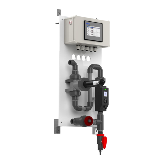
Analyzer Dimension and Mounting Figure. 1 - IK-765P-DCL Analyzer Installation 6.1. Installation Requirements Power Supply: 96-260VAC / 50-60 Hz; 60 W Inlet Water Supply: The inlet water pressure should be from 7.25 – 60 psi (0.05-0.413MPa) Outlet Water Line: This line should be returned to atmospheric sump or lower pressure recirculation line of the analyzed system water network. -
Page 9: Sample Water Connection
6.2. Sample Water Connection... -
Page 10: Display Wiring Diagram
6.3. UC-80 Display Wiring Diagram The IK-765P-DCL has universal AC power supply equipment allowing users simply to plug the power supply into a 100~240V AC 50/60Hz power outlet for normal operation. The two relay outputs are defaulted to " Passive Output ", which can be switched to " Active Output " by toggling the button on the board, as shown below in the orange box. - Page 11 The Pyxis Factory connects all pigtail output cables to the controller internally .The pigtail connection allows for rapid wiring and ease of installation. Please refer to the following diagram for the definition of each terminal. Figure. 3 - Terminal Wiring Diagram WARNING - The process of electrical connection to contact the 96-260VAC single-phase power supply, should be operated by personnel with an electrician's license.
-
Page 12: Display Pre-Wired Output Cable
6.3.1. UC-80 Display Pre-Wired Output Cable The UC-80 display and data logging terminal of the IK-765P-DCL series comes equipped with two prewired 8-pin pigtail cable with adapters. The input cable offers a male adapter for direct connection to the ST-765P Series sensor input. -
Page 13: Display Touch Screen Operation
After powering on the system, log in with the user name and password to be able to change system settings. Click the "User Login" button, select the user "pyxis", enter the password: "888888" in the user password field. A new user can be added via "User Management"... -
Page 14: Real-Time Monitoring
Click the "Enter System" button on the main interface to enter the real-time monitoring screen of the system. The data detected by the Pyxis sensors will be displayed in real-time.See a functional overview of each section of this screen highlighted below. -
Page 15: Explanation And Use Of The Hold Feature
7.5. Explanation and use of the HOLD Feature The IK-765P-DCL has an integrated HOLD feature for all Modbus TCP output parameters from the sensor that would be connected to an onsite DCS network. The purpose for this feature is to allow the user to enter a signal value HOLD on the designated parameter during periods of sensor maintenance or removal. -
Page 16: Activating The 4G Dtu Gateway/Module
7.6. Activating the 4G DTU Gateway/Module Each analyzer comes with a 4G DTU module with global SIM card to push sensor data to the Pyxis Cloud server. By default, the 4G DTU module is disabled. Please contact Pyxis Lab for pricing details and to activate the 4G DTU by emailing service@pyxis-lab.com... -
Page 17: Configurable Parameters
7.8. Configurable Parameters Click the "Parameter" button in the menu bar. Here you can select a list of options to include enter Control Interface / Settings Inferface / User Defined Settings / Diagnostic Data / 4-20mA Output Setup and Comm Setup. Figure. - Page 18 Both Relay outputs have 4 modes of operation including Disable / Manual / Periodicity and Sensor Value Figure. 17 – Relay Output Control When the mode selection is set to Disable, there will be no relay output available. Figure. 18 – Disable When the mode is selected as Manual, users can manually turn on the Output by clicking the "Turn On"...
- Page 19 When the mode selection is Periodicity, it will periodically output according to the user programmed Interval Time and Running Time Figure. 20 – Periodicity When the mode selection is Sensor Value, users can select which parameters they desire to control. See examples below.
-
Page 20: Settings Interface
7.8.2. Settings Interface Clicking on "Settings Interface" tab opens a sub-menu for Alarm Parameters and Senser Parameters. Figure. 22 –Setting Interface Alarm Parameters Setting Users can set the upper and lower alarm limits. Click "Alarm Parameters" to enter the alarm parameter settings. When the measured sensor value is lower than the set lower limit (the XX lower limit alarm) or when the measured value is higher than the set upper limit (the XX upper limit alarm), the corresponding sensor alarm will be displayed on the real-time monitoring screen. - Page 21 Sensor Parameters - Smoothing Factor Description & Adjustment In "Sensor Parameters” within the “Settings Interface" field of the "Parameter" menu, users can set the smoothing coefficient for the sensor. Usually the oxidant concentration (e.g., free chlorine) is a very small signal, which is easily subject to external interference.
- Page 22 Pyxis Lab uses the term “T90” when the measured value of the sensor reaches 90% of the true value to describe the speed of the sensor response in seconds. The default smoothing factor of ST-765P-DCL Series sensor is 0.002 (T90≈4 minutes). The available setting range of the smoothing factor is 0.001 to 0.9. The following table outlines the comparison between the smoothing factor and T90 for the ST-765P-DCL Series sensor and should be used if considering an adjustment to the smoothing factor settings.
-
Page 23: User Defined Settings
7.8.3. User Defined Settings The “User Defined” setting function allows users to assign a customized name, unit of measure and analyzer type used to any of the ST-765P-DCL Series sensor channel inputs displayed on the IK-765P-DCL. Figure. 26 – User Defined Settings Parameter Name Definition Click the orange dialog box to customize the sensor name. -
Page 24: Diagnostic Parameters For Troubleshooting Support
Figure. 29 - Diagnostic Parameters Click on “Diagnostic History Data” in the lower right corner to access to view previous diagnostic parameters. Data can also be exported and made available for support from the Pyxis Lab Service Department. Figure. 30 - Diagnostic History Data... -
Page 25: 4-20Ma Output Parameter Settings & Adjustment
7.8.5. r Settings & Adjustment 4-20mA Output Paramete Click "4-20mA Output" to enter the 4-20mA output parameter setting interface. The 4mA and 20mA output values should correspond to the default lower and upper limits of the sensor range. These values may be adjusted by the user as desired. -
Page 26: Sensor Calibration
Calibration The pH function is thoroughly calibrated at the Pyxis Lab factory prior to shipment. After removing the sensor and checking it with a pH standard buffer solution in a beaker, if the sensor value has shifted, then the user may choose from single-point, two-point or three-point calibration to re-calibrate the pH portion of the ST-765P sensor as desired. - Page 27 Single Point pH Calibration Remove the ST-765P-DCL sensor and rinse 3x with DI water ensuring there is no debris or fouling of the sensor electrode head. Submerge the sensor into a beaker with pH=7 buffer solution. Click "pH7 calibration". A dialog box will pop up to confirm whether to perform this operation, click "OK"...
- Page 28 Three Point pH Calibration Remove the ST-765P-DCL sensor and rinse 3x with DI water ensuring there is no debris or fouling of the sensor electrode head. Submerge the sensor into a beaker with pH=7 buffer solution. Click "pH7 calibration". A dialog box will pop up to confirm whether to perform this operation, click "OK"...
-
Page 29: Oxidizer Calibration
(USEPA-334.0 / ISO-7393 compliant methodology). Single Point Oxidizer Calibration (In-Situ) Use a portable or laboratory colorimeter (ie. Pyxis OxiPocket SP-200, SP-208, SP-800 or similar) to test the oxidizer concentration value of the active (flowing) water sample in the IK-765P-DCL flow reservoir. DPD methodology is recommended. - Page 30 200-800mL/min in the Tee. Use a portable or laboratory colorimeter (ie. Pyxis OxiPocket SP-200, SP-208, SP-800 or similar) to test the oxidizer concentration value of the active (flowing) water sample in the IK-765P-DCL flow reservoir.
-
Page 31: Sulfite Calibration
While the sensor is exposed to active flow of 200-800mL/min in the Tee. Enter the Sulfite concentration has been determined by the titration or dropper method (i.e. Pyxis Sulifte Dropper Kit - P/N TK35290-Z ) and ensure that the sensor reading has been stable for at least 10 minutes before calibration, click the “Process Calibration”... -
Page 32: Alarm View
7.10. Alarm View Click the "Alarm View" button on the main screen to enter the alarm view screen. Figure. 41 - Alarm View Figure. 42 - Alarm Data Query Screen In this screen users can browse all logged alarms. Drag the right scroll bar up and down to view the history of alarms. - Page 33 Historical Data Click the "Historical Data" button in the menu bar to enter the data report interface. Figure. 44 - Historical Data Screen In the data report, the user can view the stored data of all parameters. The system records sensor readings every 4 seconds by default but this can be edited by the user if desired.
- Page 34 Insert a USB disk behind the HMI display screen and enter the time range of the data to be exported in the query area. Click on the “Data Export” to download the data to the USB disk. The data quantity will be shown as a positive number if data export is successful.
-
Page 35: Historical Data Curves
7.12. Historical Data Curves Click the "Historical Curve" button in the menu bar to enter the trend curve interface. You can click the buttons below the X-axis to browse and view the values in a different time range. Click on Y-axis Range to change the minimum and maximum Y-axis values for a proper range. - Page 36 Please refer to the button description overview for Historical Curve Function navigation. Figure. 55 - Button Function Review...
-
Page 37: User Management
7.13. User Management Click the "User" button on the menu bar and then you can select "Login", "Logout" and "Manage" operations. Figure. 56 - User Management Logout enables the user to log out of the logged-in state and only view the real-time readings, but cannot perform operations such as parameter settings. -
Page 38: Modbus Register Table & Analyzer Maintenance
Modbus Register Table & Analyzer Maintenance 8.1. Modbus Correspondence Address Serial Number Definition Address Format Mode Unit Note float read-only Oxidizer (FCL/TCL) float read-only mg/L Data Sulfite float read-only mg/L Format Temp float read-only ABCD Flow float read-only mL/min FCL lower limit alarm uint read-only FCL upper limit alarm... -
Page 39: Analyzer Operation And Preventative Maintenance
/ Oxidizer Sensor Check the connection between the sensor and the circuit pH / Oxidizer Sensor No pH and Oxidizer Communication board. If the problem persists, contact Pyxis. without Communication Measurements Abnormalities pH Upper Limit pH above the Alarm... -
Page 40: Sensor Electrode Head Replacement Maintenance
Sensor Electrode Head Replacement Maintenance 9.1. Replacing pH and Oxidizer Electrode Head The EH-765-01 electrode head (P/N: 27918) of the ST-765P-DCL Series sensors can be replaced when the original electrode heads have reached the end of their working life. The typical working life of the electrode can be as long as 2-years under normal operating conditions. -
Page 41: Sensor Cleaning With Pyxis Probe Cleaning Kit
Q-tips. If the surface is not entirely clean, continue to soak the sensor for an additional time until clean. Rinse the sensor with distilled water. Pyxis Lab Probe Cleaning Kit can be purchased at our online Estore/Catalog at https://www.pyxis-lab.com/product/inline-sensor-cleaning-kit/...
Need help?
Do you have a question about the Oxipanel IK-765P-DCL and is the answer not in the manual?
Questions and answers