
Subscribe to Our Youtube Channel
Related Manuals for Pyxis OXIPANEL IK-765SS-DCL-B


Summary of Contents for Pyxis OXIPANEL IK-765SS-DCL-B
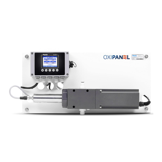
- Page 1 IK-765SS-DCL-B Free chlorine + Sulfite + pH Analyzer Industrial Chlorine Scavenger Monitor Startup Guide Pyxis Lab Inc. December 2023...
-
Page 2: Table Of Contents
Table of Contents SPECIFICATIONS ............................5 IK-765SS-B Series Panel Dimensions (mm) ....................6 IK-765SS-B Series FR-300-PLUS – Flow Reservoir Dimensions (mm) ............6 FR-300-PLUS Component Schematic ......................7 FR-300-01 Replacement Brushing Assembly Dimensions (mm) ..............7 FR-300-01 Replacement Brushing Assembly Replacement Procedure ............8 FR-300-PLUS FLOW &... - Page 3 Free-Chlorine (FCL), Sulfite (SO3), pH and Temperature utilizing proprietary Pyxis Lab smart sensor technology, coupled with a Pyxis UC-50 micro-display and data logging terminal. The IK-765SS-DCL-B also incorporates a uniquely designed automated mechanical brush flow assembly (FR-300-PLUS) which is directly controlled via the UC-50 display to maintain optimum sensor electrode cleanliness in ‘dirty’...
- Page 4 Reduce your maintenance and cost versus conventional electrochemical sensors by utilizing Pyxis replaceable Electrode Head (EH-765) for this sensor allowing for years of reliable service. The ST-765SS Series may be calibrated in-situ after cleaning via DPD or similar Sulfite wet chemistry test measurement of active sample.
-
Page 5: Specifications
CE Marked / RoHS Typical Electrode Service Life 2 years Electrode Warranty 6 Months Sensor Body Warranty 13 Months *NOTE* - Pyxis Lab is consistently updating technologies, as such, specifications may change without notice. info@pyxis-lab.com www.pyxis-lab.com Contact for details or... -
Page 6: Ik-765Ss-B Series Panel Dimensions (Mm)
IK-765SS-B Series Panel Dimensions (mm) IK-765SS-B Series FR-300-PLUS – Flow Reservoir Dimensions (mm) -
Page 7: 300-Plus Component Schematic
FR-300-PLUS Component Schematic FR-300-01 Replacement Brushing Assembly Dimensions (mm) -
Page 8: 300-01 Replacement Brushing Assembly Replacement Procedure
FR-300-01 Replacement Brushing Assembly Replacement Procedure... -
Page 9: 300-Plus Flow & Operation
100% of the time with Manual ON/OFF control of the motorized brush as a default. This is the Pyxis suggested form of operation of the FR-300-PLUS and the sensor remains wet at all times regardless of operation. This may require special installation techniques to prevent water drainage from the FR-300-PLUS during no flow periods. -
Page 10: 300-Plus Status Information
FR-300-PLUS STATUS INFORMATION The UC-50 controller supports displaying the status information of the FR-300 PLUS on the main screen, includes real-time speed value and power percentage(real-time power consumption/max power consumption). *Note*This feature is only available for UC-50 firmware version v1.0r632 and higher. *Note* (1) If UC-50 fail to connected to the FR-300-PLUS flow reservoir, status values will not be displayed. -
Page 11: Display/Data Logger Dimensions (Mm)
UC-50 DISPLAY/DATA LOGGER DIMENSIONS (mm) ST-765SS Series Sensor Dimensions (mm) ST-765SS-DCL Oxidizer + Sulfite pH Sensor... -
Page 12: Access Password
Press keys to adjust the password values. Once setting, Move the cursor to OK button to confirm the new password (as shown in figure above). *NOTE* If you forget this password, Contact Pyxis for the administrator password. -
Page 13: Terminal Board Wiring Diagram
UC-50 TERMINAL BOARD WIRING DIAGRAM Please refer to the wiring terminal diagram below for the UC-50 display/data logger. Please refer to the wiring terminal diagram below for the UC-50 display/data logger. NOTE – the UC-50 terminal board provides two prewired 8-pin pigtail cables with adapters. The input cable offers a male adapter for direct connection to the ST-765SS Series sensor input. -
Page 14: Output Signal/Relay Wiring Details And 4-20Ma Ranges
UC-50 OUTPUT SIGNAL/RELAY WIRING DETAILS AND 4-20mA RANGES. As mentioned in the previous section, the UC-50 internal terminal board is prewired with two 8-pin cable pigtail cables. The input cable (male adapter) is to be terminated the ST-765SS series sensor. The output cable (female adapter) is to be terminated to the loose flying lead cable provided with the panel and allows 2x 4-20mA output signals and 1x RS-485 signal of the ST-765SS Series sensor to be PASSED-THROUGH to another receiving device in addition to 1x 4-20mA output from the UC-50. -
Page 15: Start-Up Procedure
UC-50 START-UP PROCEDURE Click the back key on the main interface, UC-50 will UC-50 controller supports manual selection of the display the setting interface. ALL probe-related probe type or automatic identification of the probe settings and UC-50 settings can be selected on this type. -
Page 16: Setting Date & Time On Uc-50 Display
SETTING DATE & TIME ON UC-50 DISPLAY 1. Hit the Main Key 2. Hit the Up or Down Key until “System Information” is highlighted. 3. Hit the OK Key to enter the System Information Screen. 4. Hit the Down Key until the desired parameter is highlighted. 5. -
Page 17: Temperature Unit Of Measure Setup Procedure
TEMPERATURE UNIT of MEASURE SETUP PROCEDURE The display unit of temperature is Celsius by default. Users can switch the temperature unit as desired in Temp Units notification box. From the Main Menu, select Temp Units. Here you may alter between desired unit of measure for the analog output scale. -
Page 18: Setup Of User Defined Signal Input Feature
UC-50 SETUP OF USER DEFINED SIGNAL INPUT FEATURE The UC-50 supports two types of inputs starting with serial # 230143 and after: Digital Input (Pulse or Electrical Level) or Analog Input(4-20mA), which can be converted via DIP switches on UC-50 internal AI/DI module. Please use tweezers to turn the specified DIP switch to “ON”. - Page 19 Users can also enable the alarm function in Input Configuration interface. The Upper Alarm (Alarm HL) and Lower Alarm (Alarm LL) limit are constantly compared with flow rate value. Once the flow rate value exceeds the alarm upper limit or falls below the alarm lower limit, and the duration time is longer than the user programmed detection time, the flow rate value will turn red.
-
Page 20: Setup Of User Defined Analog Output Feature
# 220018 and after. This will be programmed for Temperature as a default from the Pyxis factory and s referred to in the previous section this output is internally connected to the green wire of 8-pin output pigtail table. Users can select the AOut setting interface of the UC-50 then click on the Parameter option to select the ST-765SS Series probe measurement parameters and alter the A-Out as desired. -
Page 21: User Defined Analog Output Value Settings
USER DEFINED ANALOG OUTPUT VALUE SETTINGS AO SETTING function is also on the Probe Calibration page. You can change the Free Chlorine, Sulfite, pH and Temperature values corresponding to the 20mA output to a lower value as seen in figure below. Using Sulfite as an example. Select SULFITE 20mA= [?] in Probe Calibration page. -
Page 22: Relay Configuration
UC-50 RELAY CONFIGURATION The UC-50 is equipped with relay output (24V, 8w) which is designed for alarm relay activation or may be used as desired. The UC-50 relay offers 5 modes of operation. The number of adjustable parameters will differ depending on the mode the user selects. - Page 23 4. ALARM (LL) or ALARM (HL) MODES The Turn ON and Turn OFF threshold values are constantly compared with the primary measurement of the sensor. In the case of OxiPanel, the primary measurement is oxidizer (ie. Free Chlorine) Security time is used to set the activation time of the relay in a range of 0 ~ 99999 seconds. If user does not want to limit the activation time of the relay, the security time should be set to “...
-
Page 24: Modbus Rtu Slave Station Communication Parameters
UC-50 MODBUS RTU SLAVE STATION COMMUNICATION PARAMETERS UC-50 Default Communication Parameters Device Address Baud Rate 9600 Word Length Parity None Stop Bits UC-50 Default Communication Parameters – (Writeable) Register Address Type Byte Order Register Definition 42001 Unsigned int 16 Device Address Parity 0=None 42003 Unsigned int 16... -
Page 25: Ph Process Calibration Procedure
pH PROCESS CALIBRATION PROCEDURE *NOTE* - pH process calibration is only available for ST-765SS series firmware version V3.9.1T and higher & UC-50 firmware version v1.0r638 and higher... -
Page 26: Ph Low - Calibration Procedure
pH LOW – CALIBRATION PROCEDURE pH MID (Z) – CALIBRATION PROCEDURE... - Page 27 pH HIGH – CALIBRATION PROCEDURE...
-
Page 28: Zero Free Chlorine- Calibration Procedure
ZERO FREE CHLORINE– CALIBRATION PROCEDURE SLOPE FREE CHLORINE– CALIBRATION PROCEDURE *NOTE* The ST-765SS-DCL sensor MUST be slope calibrated for Free-Chlorine based on DPD test method results of the actual system sample while installed in the FR-300-PLUS flow reservoir provided and exposed to consistent system sample flow between 200 and 800mL/minute. -
Page 29: Zero Sulfite- Calibration Procedure
ZERO SULFITE– CALIBRATION PROCEDURE SLOPE SULFITE– CALIBRATION PROCEDURE *NOTE* The ST-765SS-DCL sensor MUST be slope calibrated for Sulfite based on titration test method results of the actual system sample while installed in the FR-300-PLUS flow reservoir provided and exposed to consistent system sample flow between 200 and 800mL/minute. -
Page 30: Historical Data
HISTORICAL DATA Select Historical Data on the setting interface of the UC-50 controller, you can view the stored historical measurement data of ST-765SS. UC-50 controller stores measurement data of ST-765SS every 1 minute. You can browse the data of different time periods with the up and down keys. The data types from left to right are Free Chlorine, Sulfite, pH and Temperature. -
Page 31: Usb Function For Historical Data Upload And Frequency
USB FUNCTION FOR HISTORICAL DATA UPLOAD AND FREQUENCY UC-50 has a built-in USB interface to support historical data export and firmware upgrade function. Before accessing USB functions, please make sure USB thumb drive is properly plugged into UC-50 USB interface. For data download and upload to the UC-50 a USB device with a storage capacity between 8 and 64MB *Megabytes* is recommended. -
Page 32: Adjust Uc-50 Historical Data Log Interval
ADJUST UC-50 HISTORICAL DATA LOG INTERVAL By default, UC-50 will save sensor value every 60 seconds to its internal data storage, if an application requires 3 months historical data export, UC-50 will generate over 10,000 lines of historical data if the historical data interval is set to 60 seconds. -
Page 33: Explanation & Use Of The Signal Hold Feature
EXPLANATION & USE OF THE SIGNAL HOLD FEATURE The signal HOLD - ON/OFF feature is a function used to set and maintain the sensor output signal data at a constant value during periods when the sensor is not stable and/or fluctuating significantly due to maintenance and calibration. -
Page 34: Common Sensor Troubleshooting
Q-tips, then re-rinse. For a highly fouled sensor, soak the lower half of the sensor in 100 mL Pyxis inline sensor cleaning solution for 10-15 minutes. Gently rub the sensor electrode head with the provided Q-tips. -
Page 35: Replacing Ph / Oxidizer Electrode Head
The pH/oxidizer electrode head of ST-765SS Series can be replaced when the original electrode head reaches its working life. Order a replacement electrode head EH-765 (P/N 53061) from Pyxis and follow instructions as below. Turn off the sensor if it is powered on. -
Page 36: Order Information
ORDER INFORMATION Order Information IK-765SS-DCL-B 46758 (Auto-Brushing Free Chlorine + Sulfite + pH + Temperature Analyzer) Optional / Replacement Accessories Information ST-765SS-DCL 58444 (Free Chlorine + Sulfite + pH + Temperature w/Internal Compensation-Sensor Only) EH-765 53061 (Replacement Electrode Head for ST-765SS-Series Sensors) ZERO-OXIDIZER Calibration Standard Solution 20222 (500mL Bottle)
Need help?
Do you have a question about the OXIPANEL IK-765SS-DCL-B and is the answer not in the manual?
Questions and answers