Table of Contents
Advertisement
Quick Links
Advertisement
Table of Contents

Subscribe to Our Youtube Channel
Related Manuals for Pyxis IK-765SS-O3


Summary of Contents for Pyxis IK-765SS-O3
- Page 1 IK-765SS-O3 User Manual Pyxis Lab Inc. September 2022 - 1 -...
- Page 2 Related Statements The manufacturer shall not be liable for direct, indirect, special, incidental, or consequential damages resulting from any deficiency or omission in this manual. The manufacturer reserves the right to make changes to this manual and the products described in it at any time without notice or liability. Revised versions can be found on the manufacturer's website. Safety Information Please read this manual completely before unpacking, installing, and operating this equipment.
-
Page 3: Table Of Contents
Catalog Specifications............................. - 4 - IK-765SS-O3 Panel Features ........................- 5 - Dimension and Mounting .......................... - 6 - 3.1. Dimension..............................- 6 - 3.2. Tube Connection ............................- 6 - 3.3. Terminal Wiring ............................- 7 - Touch Screen Operation ..........................- 8 - 4.1. -
Page 4: Specifications
20% - 90% (No Condensation) Altitude <6,561 feet (<2,000 Meter) Approximate Product Weight ~ 15 kg *NOTE* - Pyxis Lab is consistently updating technologies, as such, specifications may change without notice. Contact info@pyxis-lab.com for details or www.pyxis-lab.com . - 4 -... -
Page 5: Ik-765Ss-O3 Panel Features
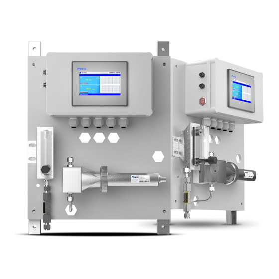
ST-765SS-O3 sensor. The inlet and outlet to the ST-007 are 316L stainless steel with SwageLok fittings in ¼-inch OD. The IK-765SS-O3 panel is also equipped with inlet PRV, Rotameter and digital Hall Effect inlet flow meter for precise control and recording of the recommended flow range of 200-400 mL/minute. The outlet flow should be diverted to drain or the inlet of the pretreatment system for those desiring NSF compliance. -
Page 6: Dimension And Mounting
Dimension and Mounting Dimension 3.1. Figure. 1 - IK-765SS-O3 controller size and installation size Power Supply: 100~240V AC 50/60Hz Water Supply: Inlet water pressure should be from 7.25 – 30 psi (0.05-0.2MPa) with an inlet feedwater line diameter of ¼- inch PE pipe. -
Page 7: Terminal Wiring
Terminal Wiring 3.3. The IK-765SS-O3 analyzer has universal AC power supply equipment allowing users simply to plug the power supply into a 100~240V AC 50/60Hz power outlet for normal operation. Warning The process of electrical connection to contact the 220V single-phase power supply, should be operated by personnel with an electrician's license. -
Page 8: Touch Screen Operation
After powering on the system, log in with the username and password to be able to change system settings. Click the "User Login" button, select the user "pyxis-User", enter the password: "888888" in the user password field. A new user can be added via "User Management" in interface of the menu. -
Page 9: Real-Time Monitoring
Click the "Enter System" button on the main interface to enter the real-time monitoring screen of the system. The data detected by the Pyxis sensors will be displayed in real-time. See a functional overview of each section of this screen highlighted below. -
Page 10: Explanation And Use Of The Hold Feature
Explanation and use of the HOLD Feature 4.4. Within the ADMIN USER ENTRY level, the IK-765SS-O3 has an integrated HOLD feature for all Modbus TCP output parameters from the sensor that would be connected to an onsite DCS network. The purpose for this feature is to allow the user to enter a signal value HOLD on the designated parameter during periods of sensor maintenance or removal. -
Page 11: Menu Bar
Figure. 8 - Hold Feature - pH Value Entry by User Figure. 9 - Hold ON interface Menu Bar 4.5. Click the button in the upper left corner of the screen to enter the system's menu interface, where the user can select to enter the desired operation interface. -
Page 12: Configurable Parameters
Configurable Parameters 4.6. Click the "Parameter" button in the menu bar. Here you can select to enter "Alarm Parameters" and "4-20mA Output" setting interface etc. Figure. 11 - Parameter Settings 4.6.1. Alar m Parameters Setting Users can set the upper and lower alarm limits. Click "Alarm Parameters" to enter the alarm parameter settings. When the measured sensor value is lower than the set lower limit (the XX lower limit alarm) or when the measured value is higher than the set upper limit (the XX upper limit alarm), the corresponding sensor alarm will be displayed on the real-time monitoring screen. -
Page 13: Sensor Parameters
4.6.2. Sensor Parameters Click ON in "Sensor Parameters" to activate the electrode properties. Activation ON will result in the electrode conducting internal cleaning voltammetry protocol for a duration of 12 seconds every 5 minutes of operation. During this time, sensor data will be suspended at previous reading value prior to activation then reinitiate after the 12 second cleaning is complete. -
Page 14: Diagnostic Parameters
4.6.4. Diagnostic Parameters Click “Diagnosis Parameters” on the diagnosis page. In the diagnosis page, the raw data measured by the probe is displayed. To help troubleshoot possible issues with the probe, please save an image of this data when the probe is placed in clean water (tap water or deionized water), in a standard, and in the sample that the probe is intended for. -
Page 15: Communication Setting
4.6.6. Communication Setting Communication parameters generally do not need to be changed. If the communication station number and other parameters need to be changed on site, they can be changed on this interface. Figure. 17 - Modbus RTU Figure. 18 - Modbus TCP Calibration 4.7. -
Page 16: Ph Calibration
4.7.1. pH Calibration The pH function is thoroughly calibrated at the Pyxis Lab factory. After checking with a pH standard buffer solution, if the sensor value has shifted, then the user may choose from single-point, two-point or three-point calibration to re- calibrate the pH portion of the ST-765SS-O3 sensor as desired. -
Page 17: O3 Calibration
Calibration of the ST-765SS-O3 sensor for ozone should be done with the sensor inline exposed to active flowing sample water. Use a portable or laboratory colorimeter (i.e. Pyxis SP-200 / SP-800 / SP-910 or similar) to test the active (flowing) water sample in the flow tee assembly of the IK-765SS-O3 panel. Once you have tested and confirmed the concentration value in the active (flowing) flow tee assembly, enter the test result value of the portable or laboratory colorimeter in Calibration Screen and click "High Cal". -
Page 18: Alarm View
Figure. 22 - O3 Calibration Figure. 23 - Awaiting execution Screen of O3 Calibration Alarm View 4.8. Click the "Alarm View" button on the main screen to enter the alarm view screen. Figure. 24 - Alarm View In this screen users can browse all logged alarms. Drag the right scroll bar up and down to view the history of alarms. Click "Previous"... -
Page 19: Historical Data
Figure. 25 - Alarm Data Query Screen The Delete button in the lower left corner will delete all alarm records. After clicking delete, you must exit the screen and reenter before the historical data within the data report is cleared. Historical Data 4.9. - Page 20 Figure. 27 Data Storage Cycle Time Setting Click “Delete” in the lower left corner. After entering the retention time, click the “Delete” button to clear all historical data within the retention time range. Figure. 28 - History Data Deletion Screen Click the “Query “button in the lower right corner, enter the start time and end time and then click the “Query”...
-
Page 21: Historical Data Curves
4.10. Historical Data Curves Click the "Historical Curve" button in the menu bar to enter the trend curve interface. You can click the buttons below the X-axis to browse and view the values in a different time range. Click on Y-axis Range to change the minimum and maximum Y-axis values for a proper range. -
Page 22: User Management
Figure. 33 - Time Setting Screen 4.11. User Management Click the "User" button on the menu bar and then you can select "Login", "Logout" and "Manage" operations. Figure 40. – User Management Logout enables the user to log out of the logged-in state and only view the real-time readings but cannot perform operations such as parameter settings. - Page 23 Modify Password: Select the user you want to change, then click Modify User button, enter the user's own password in the User Password column and Confirm Password column, and click Confirm to modify successfully. *NOTE* If you do not want to set the password, you can delete the password and save it. Figure.
-
Page 24: Maintenance
Operation and Maintenance 5.2. After the analyzer is installed by a qualified technician, it can begin to monitor water quality. The IK-765SS-O3 is designed to be simple to operate, but still requires some regular maintenance. Actual system maintenance may vary depending on the installation conditions and usage. -
Page 25: Instrument Alarms And Descriptions
Instrument Alarms and Descriptions 5.3. Please refer to the instrument alarms and descriptions table when troubleshooting the IK-765SS-O3 issues an alarm or indicates abnormal measurement data. Table. 3 Common Alarms Alarms Description Symptoms Solutions/Recommendations PLC Communication PLC without Check if the wiring inside the PLC and control... -
Page 26: Replacing Ph And Oxidizer Electrode Head
The pH/oxidizer electrode head of ST-765SS-O3 sensor can be replaced when the original electrode head reaches its working life. Order a replacement electrode head EH-765-O3 (P/N 22603) from Pyxis and follow instructions below. Turn off the sensor if it is powered on. -
Page 27: Order Details
Stainless Steel Hall Effect Digital Flow Meter 22501 (1/4-inch OD) UC-80 Display + Data Logging Terminal 14003 (Replacement) Pyxis pH Combo Calibration Pack 57007 (pH 4-7-10 Calibration Solution 3-Pack - 500mL ea.) SP-200 OxiPocket 50802 (Pocket All-Oxidizing Disinfectants Colorimeter & Fluorometer) Contact Pyxis Lab info@pyxis-lab.com...
Need help?
Do you have a question about the IK-765SS-O3 and is the answer not in the manual?
Questions and answers