Table of Contents
Advertisement
Quick Links
Advertisement
Table of Contents

Subscribe to Our Youtube Channel
Related Manuals for Pyxis IK-73 PLUS Series


Summary of Contents for Pyxis IK-73 PLUS Series
- Page 2 Related Statements The manufacturer shall not be liable for direct, indirect, special, incidental or consequential damages resulting from any deficiency or omission in this manual. The manufacturer reserves the right to make changes to this manual and the products described in it at any time without notice or liability. Revised versions can be found on the manufacturer's website.
-
Page 3: Table Of Contents
Modbus Communication & Recommended Maintenance ................ - 28 - 7.1. Modbus Correspondence Address ......................- 28 - 7.2. Suggested Maintenance ...........................- 28 - Replacing the FT-100-PLUS Brush & Seal Assembly .................. - 29 - Contact Pyxis Lab ............................. - 30 -... -
Page 4: Specifications
Dimensions (HxWxD) Panel (IK-73X9-PLUS) 750H x 450W x 243D mm Approximate Product Weight IK-73X-PLUS Series ~ 15 kg *As Pyxis technology is continuously updated, this technical parameter may change at any time without notice Order Information IK-739-PLUS 12001 (Auto Brushing Turbidity Analyzer 0.000 – 40.000 NTU)) -
Page 5: Unpackaging
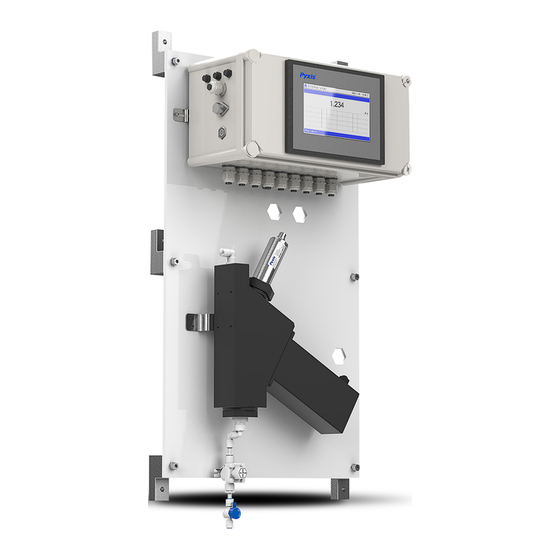
The IK-73X-PLUS series offers highly accurate, auto-brushing, real-time measurement, display and data- logging of Ultra-Low Turbidity, utilizing proprietary Pyxis Lab smart sensor technology, coupled with a Pyxis touch screen display and data logging terminal. The IK-739-PLUS measures a range of 0.000 – 40.00 NTU while the IK-736-PLUS measures a range of 0.000 –... -
Page 6: Dimension And Mounting
Pyxis FT-100-PLUS auto-brushing flow reservoir with motorized mechanical cleaning of the sensor optical lense enabling the highest resolution possible of 0.002NTU with unmatched stability. The LT- 739 and LT-736 both offer simple calibration via the Pyxis L-CAL Portable Turbidity Calibration Kit as outlined in this manual. - Page 7 UC-100A Display/Data Logger Dimensions (mm) Figure. 3-UC-100A Sensor Diagrams (mm) Figure. 4-LT-739 / LT-736 Turbidity Sensor - 4 -...
-
Page 8: Installation
Installation 5.1. Installation Requirements Power Supply: 100~240V AC 50/60Hz Water Supply: Inlet water pressure should be from 7.25 – 30 psi (0.05-0.2MPa). The FT-100-PLUS brushing flow reservoir will come equipped with inlet feedwater line adapter of ¼-inch OD tubing connected to ½-inch FNPT inlet. -
Page 9: Terminal Wiring
5.3. Terminal Wiring The IK-739-PLUS and IK-736-PLUS analyzers have universal AC power supply equipment allowing users simply to plug the power supply into a 100~240V AC 50/60Hz power outlet for normal operation. WARNING The process of electrical connection to contact the 220V single-phase power supply, should be operated by personnel with an electrician's license. -
Page 10: Touch Screen Operation
After powering on the system, log in with the user name and password to be able to change system settings. Click the "User Login" button, select the user "pyxis", enter the password: "888888" in the user password field. A new user can be added via "User Management" in interface of the menu. -
Page 11: Real-Time Monitoring
Click the "Enter System" button on the main interface to enter the real-time monitoring screen of the system. The data detected by the Pyxis sensors will be displayed in real-time. See a functional overview of each section of this screen highlighted below. (numbers 1-4) -
Page 12: Menu Bar
Press and hold the curve area for 2 seconds and then let go, the Y-axis curve range setting dialog box will appear. Users may change the display value range of Y-axis for each measurement index curve. Click the outter area of the screen to save and exit the setting screen after modifications are made. NOTE the upper value should correspond with the turbidity sensors range and typical application conditions. -
Page 13: Configurable Parameters
6.5. Configurable Parameters Click the "Parameter" button in the menu bar. Here you can select to enter "Alarm Parameters" and "4- 20mA Output" setting interface etc. Figure 11 - Parameter Settings 6.5.1. Alarm Parameter Setting When the online user has the right to operate, upper and lower alarm limits can be set. Click "Alarm Parameter "... -
Page 14: Name Definition
6.5.2. Name Definition Click the orange dialog box to customize the sensor name. Here users can also change the unit of measure for temperature display. Figure 13 - Name Definition 6.5.3. Sensor Figure. 14-Sensor Diagnostic Parameters Click “Diagnosis Parameters” to the diagnosis page. In the diagnosis page, the raw data measured by the sensor is displayed. -
Page 15: Model Selection
Figure 15 - Diagnostic Parameters Model Selection The corresponding sensor model will be selected in the factory, if the sensor is replaced, please select the new sensor model in this interface and follow the prompts to operate step by step. Figure. - Page 16 Figure. 17 - Model Selection-2 Figure. 18 - Model Selection-3 - 13 -...
-
Page 17: Cleaning Parameters Setting
6.5.4. Setting Cleaning Parameters The IK-73X-PLUS offers an auto-brushing flow reservoir for the LT-739 and LT-736 turbidity sensors. When entering the cleaning control parameter setting interface for the first time, a notice screen will appear to ensure the panel has the auto-brushing assembly in place (FT-100-PLUS). After confirming that the cleaning control module is installed, click Enable to enter the parameter setting interface. -
Page 18: 4-20Ma Output Parameters Setting
6.5.5. 4-20mA Output Parameters Setting Click "4-20mA Output " to enter the 4-20mA output parameter setting interface. The 4mA and 20mA output values should corresponds to the lower and upper limits of the sensor range or range of application use. Default 4-20mA output values are provided in Figure. *NOTE* The closer the value is set to the measurement value the more precise the data. -
Page 19: Calibration
Figure 23 - Modbus TCP 6.6. Calibration Click on the "Calibration" button in the menu bar and select the sensor to be calibrated. Figure 24 - Sensor Calibration - 16 -... - Page 20 The LT-739 and LT-736 Ultra Low Turbidity Sensors are rigorously calibrated at the Pyxis Lab factory. If the sensor is kept clean, the user will not need to calibrate the sensor for one year of operation. However, the user may calibrate the sensor as desired. *NOTE* Pyxis recommends the sensor be calibrated to the application range of its use only.
- Page 21 Mid-Range Calibration using the L-CAL Portable Turbidity Calibration Kit: If a mid-range calibration is not required, the user does not need to perform a mid-range calibration of the LT-739 or LT-736 sensor. If a mid calibration is required, proceed by rinsing the L-CAL vessel with Deionized water and refill with 500mL of known turbidity standard solution between 5NTU and 10NTU for LT-739 mid-range calibration and between and between 5NTU and 50NTU for LT-736 mid-range calibration.
- Page 22 LT-739 / LT-736 Calibration using L-CAL Portable Turbidity Calibration Kit Pyxis Lab has developed L-CAL as a portable and reusable liquid-state turbidity calibration kit for rapid calibration of the all LT-73X Series inline ultra-low turbidity sensors. The L-CAL calibration kit allows...
- Page 23 - 20 -...
-
Page 24: Recovering Data
6.7. Recovering Data Click the restore button in the calibration interface of each sensor to restore the data of the turbidity sensor. If a user error is made during calibration and other operations, you may restore the factory settings of the sensor through the restore function. -
Page 25: Historical Data
In this screen users can browse all logged alarms. Drag the right scroll bar up and down to view the history of alarms. Click "Previous" and "Next" to advance to the next page. Click “Query” then enter the alarm number in the pop-up box to query that alarm. Figure 29 - Alarm Data Query Screen The Delete button in the lower left corner will delete all alarm records. - Page 26 In the data report, the user can view the stored data of all parameters. The system records sensor readings every 4 seconds by default but this can be edited by the user if desired. Drag the scroll bar on the right to slide up or down or click "Previous"...
- Page 27 Click the “Query”button in the lower right corner, enter the start time and end time and then click the “Query” button. Note that the start time and end time must be filled in exactly and completely according to the system time format. Figure 33 - Historical Data Query and Export Screen Insert a USB disk behind the display screen and enter the time range of the data to be exported in the query area.
-
Page 28: Historical Data Curves
6.10. Historical Data Curves Click the "Historical Curve" button in the menu bar to enter the trend curve interface. You can click the buttons below the X-axis to browse and view the values in a different time range. Click on Y-axis Range to change the minimum and maximum Y-axis values for a proper range. -
Page 29: User Management
Figure 37 - Time Setting Screen 6.11. User Management Click the "User Management" button on the menu bar and then you can select "Login", "Logout" and "Manage" operations. Figure 38 - User Management Logout enables the user to log out of the logged-in state and only view the real-time readings, but cannot perform operations such as parameter settings. - Page 30 Figure 39 - User Management Screen Modify Password: Select the user you want to change, then click Modify User button, enter the user's own password in the User Password column and Confirm Password column, and click Confirm to modify successfully. *NOTE* If you do not want to set the password, you can delete the password and save it. Figure 40 - Modifying the User Screen - 27 -...
-
Page 31: Modbus Communication & Recommended Maintenance
Modbus Communication & Recommended Maintenance 7.1. Modbus Correspondence Address Number Definition Address Format Mode Unit Note Turbidity float Read only Data format: ABCD Turbidity Sensor Communication uint Read only Abnormal uint Read only Turbidity Upper Limit Alarm uint Read only 0: Normal Turbidity lower limit alarm 1: Alarm... -
Page 32: Replacing The Ft-100-Plus Brush & Seal Assembly
The IK-739-PLUS and IK-736-PLUS panels come equipped with FT-100-PLUS automatic brush assembly for inline sensor cleaning and air bubble removal. Replacement of the FTP-100-1 brush and seal assembly (Pyxis P/N 28698) should be conducted annually or as needed by following the process steps below. Contact Pyxis Lab for pricing details. - Page 33 Contact Us Pyxis Lab Inc. 21242 Spell Circle Tomball, TX. 77375 info@pyxis-lab.com for general inquiries service@pyxis-lab.com for technical service and support order@pyxis-lab.com for order and pricing inquires 1-866-203-8397 Phone USA for all needs Office Hours 7AM – 5PM Central Time USA...
Need help?
Do you have a question about the IK-73 PLUS Series and is the answer not in the manual?
Questions and answers