Table of Contents
Advertisement
Quick Links
Advertisement
Table of Contents

Related Manuals for Pyxis OxiPanel PLUS Industrial IK-765-BP


Summary of Contents for Pyxis OxiPanel PLUS Industrial IK-765-BP
- Page 2 Related Statements The manufacturer shall not be liable for direct, indirect, special, incidental or consequential damages resulting from any deficiency or omission in this manual. The manufacturer reserves the right to make changes to this manual and the products described in it at any time without notice or liability. Revised versions can be found on the manufacturer's website.
-
Page 3: Table Of Contents
Table of Contents Specifications ............................. - 1 - Product Description ........................... - 2 - Features ..............................- 3 - Part Numbers & Ordering Details ....................... - 4 - Analyzer Dimension and Mounting ......................- 5 - Analyzer Installation ..........................- 5 - 6.1. - Page 4 Instrument Alarms and Descriptions ....................- 42 - Replacement Maintenance ....................... - 43 - 11.1. Replacing the FR-300-PLUS Brush Assembly ...................- 43 - 11.2. Replacing pH and Oxidizer Electrode Head..................- 44 - 11.3. Sensor Cleaning with Pyxis Probe Cleaning Kit ................- 45 -...
-
Page 5: Specifications
6 Months Electrode / 13 Months Sensor Body & Panel Typical Electrode Service Life 2 years Typical FR-300-PLUS Brush Life 12-18 months depending on application of use Pyxis 4G CloudLink Included & Activated On Request with Enrollment – Contact Pyxis Lab for details - 1 -... -
Page 6: Product Description
(FCL), sulfite (SO3), pH, and temperature of the sample water with oxidizer compensation based on the pH and temperature of sample conditions present in the application of use. This Pyxis sensor design is membrane-free and based on unique principles and incorporates Pyxis' advanced technology in the field of bare-gold electrochemical detection. -
Page 7: Features
The OxiPanel-PLUS contains the Pyxis 4G CloudLink and global SIM card as a comprehensive data gateway ⚫ to cloud device for live mobile APP trend view, data download and reporting. Contact Pyxis for details. - 3 -... -
Page 8: Part Numbers & Ordering Details
Flow Regulating Motorized Valve w/4-20mA Control 21972 (Replacement) UC-80 Display + Data Logging Terminal 14003 (Replacement) Pyxis pH Combo Calibration Pack 57007 (pH 4-7-10 Calibration Solution 3-Pack - 500mL ea.) Pyxis Zero Oxidizer Calibration Standard 21022 (0ppm Oxidizer Solution – 500mL) -
Page 9: Analyzer Dimension And Mounting
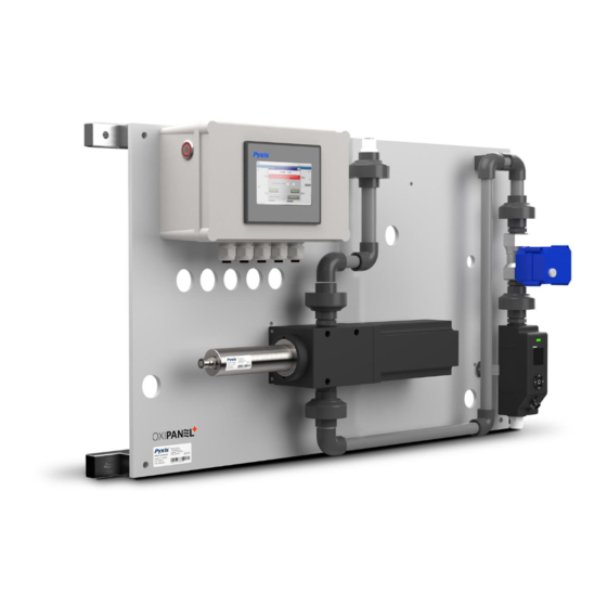
Analyzer Dimension and Mounting Figure. 1 - OxiPanel-PLUS IK-765SS-BP Series Analyzer Installation 6.1. Installation Requirements Power Supply: 96-260VAC / 50-60 Hz; 60 W Inlet Water Supply: The inlet water pressure should be from 7.25 – 60 psi (0.05-0.413MPa) with an inlet feedwater line diameter of ⅜-inch OD tubing adapter threaded into ½-inch FNPT socket. -
Page 10: Sample Water Connection
6.2. Sample Water Connection Sample Water Inlet: Connect the inlet water ⅜-inch OD tubing to the quick adapter provided. Sample Water Outlet: Connect the outlet water ⅜-inch OD tubing to the quick adapter provided. *NOTE* OD Tubing adapters are provided as a convenience. If desired, users may remove the ⅜-inch OD tubing adapter and directly plump the sample water inlet/outlet via ½-inch NPT piping to the OxiPanel-PLUS analyzer. -
Page 11: Terminal Board Wiring
6.3. Terminal Board Wiring UC-80 Display Wiring Diagram 6.3.1. The OxiPanel-PLUS IK-765-BP series has universal AC power supply equipment allowing users simply to plug the power supply into a 100~240V AC 50/60Hz power outlet for normal operation. The two relay outputs are defaulted to "Active Output", which can be switched to "Passive Output" by toggling the button on the board, as shown below in the orange box. - Page 12 The Pyxis Factory connect all pigtail output cables to the controller internally except for relay #1. The pigtail connection allows for rapid wiring and ease of installation. Please refer to the following diagram for the definition of each terminal. Relay #1 is available for customer use when wired internally to terminal block.
-
Page 13: Display Pre-Wired Output Cable
6.3.2. UC-80 Display Pre-Wired Output Cable The UC-80 display and data logging terminal of the OxiPanel-PLUS IK-765-BP series comes equipped with two prewired 8-pin pigtail cable with adapters. The input cable offers a male adapter for direct connection to the ST- 765SS Series sensor input. -
Page 14: Analyzer Components & Dimensions
Analyzer Components & Dimensions 7.1. UC-80 Display & Data Logging Terminal (mm) 7.2. FS-100 Ultrasonic Flow Meter (mm) - 10 -... -
Page 15: 300-Plus Automatic Brushing Flow Assembly (Mm)
7.3. FR-300-PLUS Automatic Brushing Flow Assembly (mm) 7.4. ST-765SS Series Sensor (mm) - 11 -... -
Page 16: Fs-100 Flow Control Module Overview & Use
The Flow Control Module is a stand-alone water flow measurement and control solution, a unique platform that provides accurate flow measurement and regulation. The Flow Control Module is equipped with the Pyxis FS-100 ultrasonic flow meter with display, which allows direct control of pre-installed regulating valves through a simple user programmable interface and a measurement range of 0 –... -
Page 17: Fs-100 Main Screen
8.2. FS-100 Main Screen Main Screen Description Description Flow Detection Mode Working Status (same color as LED status indicator) Flow Rate Value Timer (unit: auto range) Unit of measured flow value Accumulated Flow Value (unit: auto range) R = Average Flow Rate Mode M = Instantaneous Flow Rate Mode C = Flow Rate Control Mode *NOTE* For C-Mode refer to Section 7.4 for programming details. -
Page 18: Fs-100 - Setting The C-Mode For The Sample Flow Control
8.4. FS-100 - Setting the C-Mode for the Sample Flow Control The Oxipanel PLUS series are programmed to use the Flow Rate Control (C) mode by default, which does not need to be changed by the customer. If a change to measure only is desired (with no control) users may follow the steps below to adjust the FS-100 functional settings. -
Page 19: Fs-100 Modbus Communication Settings
8.5. FS-100 Modbus Communication Settings Press in the setting menu and select [Com] to modify communication parameters (Figure 7). The following communication settings are pre-programmed into the FS-100 for direct communication with the OxiPanel PLUS display interface. *IMPORTANT NOTE* These values should NOT BE ALTERED, otherwise flow control failure will occur. -
Page 20: Fs-100 Device Information & Diagnosis
[Info]. This screen contains the device name, serial number, software version, and hardware version. Provide an image of both the DEVICE INFORMATION screen and the DIAGNOSIS screen when you contact Pyxis (service@pyxis-lab.com) for troubleshooting your device or call +1 (866) 203-8397 ext 2. -
Page 21: Display Touch Screen Operation
After powering on the system, log in with the user name and password to be able to change system settings. Click the "User Login" button, select the user "pyxis", enter the password: "888888" in the user password field. A new user can be added via "User Management"... -
Page 22: Real-Time Monitoring
9.4. Activating the 4G DTU Gateway/Module Each OxiPanel Plus comes with a 4G DTU module with global SIM card to push sensor data to the Pyxis Cloud server. By default, the 4G DTU module is disabled. Please contact Pyxis Lab for pricing details and to activate the 4G DTU by emailing service@pyxis-lab.com... -
Page 23: Menu Bar
9.5. Menu Bar Click the button in the upper left corner of the screen to enter the system's menu interface, where the user can select to enter the desired operation interface. Figure. 14 - Menu Bar 9.6. Configurable Parameters Click the "Parameter" button in the menu bar. Here you can select a list of options to include enter Control Interface / Settings Inferface / User Defined Settings / Diagnostic Data / 4-20mA Output Setup and Comm Setup. -
Page 24: Control Interface
Control Interface 9.6.1. Clicking on "Control Interface" opens a sub-menu for Flow Interlock Control and Relay Output Control. Figure. 16 - Control Interface Flow Interlock Control In the "Flow Interlock" users can select the flow interlocked control mode for the FR-300-PLUS brushing reservoir as well as the ST-765SS Series sensor of the OxiPanel PLUS system being used. -
Page 25: Relay Output Control
Figure. 18A - Flow Interlock Control - Automatic Mode Figure. 18B - Numeric Display "---" with Flow <50mL/min *NOTE* In the event of a sudden power loss, the Flow Interlock Control mode will return to the same settings that were programmed before the power failure. Relay Output Control The OxiPanel PLUS has two (2) 24VDC relay outputs. - Page 26 Both Relay outputs have 4 modes of operation including Disable / Manual / Periodicity and Sensor Value Figure. 20 – Relay Output Control When the mode selection is set to Disable, there will be no relay output available. Figure. 21 – Disable When the mode is selected as Manual, users can manually turn on the Output by clicking the "Turn On"...
- Page 27 When the mode selection is Periodicity, it will periodically output according to the user programmed Interval Time and Running Time Figure. 23 – Periodicity When the mode selection is Sensor Value, users can select which parameters they desire to control. See examples below.
-
Page 28: Settings Interface
Settings Interface 9.6.2. Clicking on "Settings Interface" tab opens a sub-menu for Alarm Parameters and Senser Parameters. Figure. 25 –Setting Interface Alarm Parameters Setting Users can set the upper and lower alarm limits. Click "Alarm Parameters" to enter the alarm parameter settings. When the measured sensor value is lower than the set lower limit (the XX lower limit alarm) or when the measured value is higher than the set upper limit (the XX upper limit alarm), the corresponding sensor alarm will be displayed on the real-time monitoring screen. - Page 29 Figure. 28 - Smoothing Coefficient Pyxis Lab uses the term “T90” when the measured value of the sensor reaches 90% of the true value to describe the speed of the sensor response in seconds. The default smoothing factor of ST-765SS Series sensor is 0.002 (T90 ≈4 minutes).
-
Page 30: User Defined Settings
User Defined Settings 9.6.3. The “User Defined” setting function allows users to assign a customized name, unit of measure and analyzer type used to any of the ST-765SS Series sensor channel inputs displayed on the OxiPanel PLUS. Figure. 29 – User Defined Settings Parameter Name Definition Click the orange dialog box to customize the sensor name. -
Page 31: Diagnostic Parameters For Troubleshooting Support
(tap water or deionized water), in a standard, and in the sample that the probe is intended for. These images may be sent to service@pyxis-lab.com for troubleshooting support. Figure. 33 - Diagnostic Parameters... -
Page 32: 4-20Ma Output Parameter Settings & Adjustment
Click on “Diagnostic History Data” in the lower right corner to access to view previous diagnostic parameters. Data can also be exported and made available for support from the Pyxis Lab Service Department. Figure. 34 - Diagnostic History Data Figure. 35 - Diagnostic History Data Query r Settings &... -
Page 33: Modbus Communication Settings
UC-80 Modbus Communication Settings 9.6.6. If the site desires to connect the UC-80 outputs to a DCS (Distributed Control System) for the purposes of information and process control, users can connect the master station device to the UC-80 through the HMI (Human Machine Interface) terminal and read the data according to the parameter register table provided in Section 10.1 of this manual) Modbus RTU (RS-485) and Modbus TCP and Ethernet Address settings are preset but may be altered by the user... -
Page 34: Ph Calibration
Calibration The pH function is thoroughly calibrated at the Pyxis Lab factory prior to shipment. After removing the sensor and checking it with a pH standard buffer solution in a beaker, if the sensor value has shifted, then the user may choose from single-point, two-point or three-point calibration to re-calibrate the pH portion of the ST-765SS sensor as desired. - Page 35 Two Point pH Calibration Remove the ST-765SS sensor and rinse 3x with DI water ensuring there is no debris or fouling of the sensor electrode head. Submerge the sensor into a beaker with pH=7 buffer solution. Click "pH7 calibration". A dialog box will pop up to confirm whether to perform this operation, click "OK"...
-
Page 36: Oxidizer Calibration
(USEPA-334.0 / ISO-7393 compliant methodology). Single Point Oxidizer Calibration (In-Situ) Use a portable or laboratory colorimeter (ie. Pyxis OxiPocket SP-200, Pyxis SP-800 or similar) to test the oxidizer concentratoin value of the active (flowing) water sample in the OxiPanel PLUS flow reservoir. DPD methodology is recommended. - Page 37 Two Point Oxidizer Calibration *NOTE* Under normal operational use of the ST765SS Series sensor, Pyxis Lab does not suggest a Zero-Point calibration by the user and the preprogrammed factory zero should remain unaltered. Only Slope calibration is recommended as a standard practice.
-
Page 38: Sulfite Calibration
*NOTE* Under normal circumstances, the ZERO calibration of the ST-765 series sensor is not recommended or required, Pyxis Lab suggests High calibration only, unless otherwise directed via Pyxis Lab technical support team. Please refer to the High calibration procedure section for details. -
Page 39: Alarm View
9.8. Alarm View Click the "Alarm View" button on the main screen to enter the alarm view screen. Figure. 47 - Alarm View Figure. 48 - Alarm Data Query Screen In this screen users can browse all logged alarms. Drag the right scroll bar up and down to view the history of alarms. -
Page 40: Historical Data - Query, View & Usb Download
9.9. Historical Data – Query, View & USB Download Click on "Data" to view historical data and calibration logs. Figure. 49 - Data Historical Data Click the "Historical Data" button in the menu bar to enter the data report interface. Figure. - Page 41 Click the “Query” button in the lower right corner, enter the start time and end time and then click the “Query” button.*NOTE* The start time and end time must be filled in exactly and completely according to the system time format of Year / Month / Day / Hours / Minutes / Seconds.
-
Page 42: Historical Data Curves
Calibration Log The calibration log can be viewed in the calibration log interface, and when the export operation is performed, the diagnostic parameters, historical data, and calibration log will be exported simultaneously. Figure. 54 - Calibration Log Figure. 55 - Calibration Log Query/Export 9.10. -
Page 43: User Management
Figure. 60 - Time Setting Screen Please refer to the button description overview for Historical Curve Function navigation. Figure. 61 - Button Function Review 9.11. User Management Click the "User" button on the menu bar and then you can select "Login", "Logout" and "Manage" operations. Figure. - Page 44 Logout enables the user to log out of the logged-in state and only view the real-time readings, but cannot perform operations such as parameter settings. Click “Manage” to enter the user management interface, where you can add users, change passwords and other operations. Users can set their own user name and password and select the user group they belong to.
-
Page 45: Modbus Register Table & Analyzer Maintenance
Modbus Register Table & Analyzer Maintenance 10.1. Modbus Correspondence Address Serial Number Definition Address Format Mode Unit Note Oxidizer Concentration 1 float read-only mg/L float read-only Data Sulfite 2 float read-only mg/L Format ABCD Temperature float read-only Flow Rate uint read-only mL/min Concentration1 Lower Limit Alarm... -
Page 46: Analyzer Operation And Maintenance
/ Oxidizer Sensor Check the connection between the sensor and the circuit pH / Oxidizer Sensor No pH and Oxidizer Communication board. If the problem persists, contact Pyxis. without Communication Measurements Abnormalities pH Upper Limit pH above the Alarm... -
Page 47: Replacement Maintenance
Replacement Maintenance 11.1. Replacing the FR-300-PLUS Brush Assembly Under normal application use, the FR-300-PLUS brush replacement should be done every 2-years. This may vary depending on application and water quality. Please refer to the following process steps for replacement of the FR-300-01 (P/N : 50700-A49) brush assembly. -
Page 48: Replacing Ph And Oxidizer Electrode Head
11.2. Replacing pH and Oxidizer Electrode Head The EH-765 electrode head (P/N: 53061) of the ST-765SS Series sensors can be replaced when the original electrode heads have reached the end of their working life. The typical working life of the electrode can be as long as 2-years under normal operating conditions. -
Page 49: Sensor Cleaning With Pyxis Probe Cleaning Kit
If the FR-300-PLUS brush is in need of replacement, refer to Section 11.1 of this manual. Soak the lower half of the ST-765S Series sensor in 100 mL Pyxis Probe Cleaning Solution for 10-15 minutes. Gently wipe the sensor electrode head with the provided Q-tips. If the surface is not entirely clean, continue to soak the sensor for an additional time until clean.
Need help?
Do you have a question about the OxiPanel PLUS Industrial IK-765-BP and is the answer not in the manual?
Questions and answers