Table of Contents
Advertisement
Quick Links
Advertisement
Table of Contents

Related Manuals for Pyxis IK-76SSS-S03


Summary of Contents for Pyxis IK-76SSS-S03
- Page 1 V1.2...
- Page 2 Related Statements The manufacturer shall not be liable for direct, indirect, special, incidental, or consequential damages resulting from any deficiency or omission in this manual. The manufacturer reserves the right to make changes to this manual and the products described in it at any time without notice or liability. Revised versions can be found on the manufacturer's website.
-
Page 3: Table Of Contents
Catalog Specifications ............................. - 1 - IK-765SS-SO3 Panel Features ........................- 2 - Dimension and Mounting........................... - 3 - 3.1. Dimension ..............................- 3 - 3.2. Tube connection ............................- 3 - 3.3. Terminal Wiring ............................- 4 - Touch Screen Operation ..........................- 5 - 4.1. -
Page 4: Specifications
Typical Electrode Service Life 2 years Electrode Warranty 6 Months Sensor Body Warranty 13 Months *NOTE* - Pyxis Lab is consistently updating technologies, as such, specifications may change without notice. Contact info@pyxis-lab.com for details or www.pyxis-lab.com . - 1 -... -
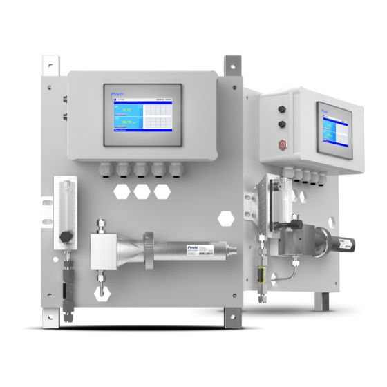
Page 5: Ik-765Ss-So3 Panel Features
Reduce your maintenance and cost versus conventional electrochemical sensors by utilizing Pyxis replaceable Electrode Head (EH-765) for this sensor allowing for years of reliable service. The ST- 765SS Series may be calibrated in-situ after cleaning via DPD or similar Sulfite wet chemistry test measurement of active sample. -
Page 6: Dimension And Mounting
Dimension and Mounting 3.1. Dimension Figure. 1 - IK-765SS-SO3 controller size and installation size Power Supply: 100~240V AC 50/60Hz Water Supply: Inlet water pressure should be from 7.25 – 30 psi (0.05-0.2MPa) with an inlet feedwater line diameter of ¼- inch OD. -
Page 7: Terminal Wiring
3.3. Terminal Wiring The IK-765SS-SO3 analyzer has universal AC power supply equipment allowing users simply to plug the power supply into a 100~240V AC 50/60Hz power outlet for normal operation. Warning The process of electrical connection to contact the 220V single-phase power supply, should be operated by personnel with an electrician's license. -
Page 8: Touch Screen Operation
Touch Screen Operation 4.1. Main Screen After the system is powered on an initial screen allows the user to log into the system. Figure. 3 - Main Screen 4.2. User Login After powering on the system, log in with the username and password to be able to change system settings. Click the "User Login"... -
Page 9: Real-Time Monitoring
Click the "Enter System" button on the main interface to enter the real-time monitoring screen of the system. The data detected by the Pyxis sensors will be displayed in real-time. See a functional overview of each section of this screen highlighted below. -
Page 10: Menu Bar
4.4. Menu Bar Click the button in the upper left corner of the screen to enter the system's menu interface, where the user can select to enter the desired operation interface. Figure. 7 - Menu Bar 4.5. Configurable Parameters Click the "Parameter" button in the menu bar. Here you can select to enter "Alarm Parameters" and "4-20mA Output" setting interface etc. -
Page 11: Name Definition
Figure. 9 - Alarm Parameter Setting 4.5.2. Name Definition Click the orange dialog box to customize the sensor name. Figure. 10 - Name Definition 4.5.3. Diagnostic Parameters Click “Diagnosis Parameters” to the diagnosis page. In the diagnosis page, the raw data measured by the probe is displayed. To help troubleshooting possible issues with the probe, please save an image of this data when the probe is placed in a clean water, in a standard, and in the sample that the probe is intended for. -
Page 12: 4-20Ma Output Parameters Setting
4.5.4. 4-20mA Output Parameters Setting Click "4-20mA Output " to enter the 4-20mA output parameter setting interface. The 4mA and 20mA output values should corresponds to the lower and upper limits of the sensor range. *NOTE* The closer the value is set to the measurement value the more accurate the data. -
Page 13: Calibration
Calibration The pH function is thoroughly calibrated at the Pyxis Lab factory. After checking with a pH standard buffer solution, if the sensor value has shifted, then the user may choose from single-point, two-point or three-point calibration to re-calibrate the pH portion of the ST-765SS-SO3 sensor as desired. - Page 14 Single Point pH Calibration Remove the ST-765SS-SO3 sensor and rinse 3x with DI water. Submerge the sensor into a beaker with pH=7 buffer solution. Click "pH7 calibration". A dialog box will pop up to confirm whether to perform this operation, click "OK" if the calibration operation is confirmed, if the calibration is successful the dialog box will show "calibration success".
-
Page 15: So3 Calibration
Calibration of the ST-765SS-SO3 sensor for Sulfite should be done with the sensor inline exposed to active flowing sample water. Use titration, colorimeter or fluorometer methods (i.e. Pyxis SP-800 / SP-910, Hach DR-1300 or similar) to test the active (flowing) water sample in the flow tee assembly of the IK-765SS-SO3 panel. Once you have tested and confirmed the Sulfite concentration value in the active (flowing) flow tee assembly, enter the recorded test result value in Calibration Screen and click "High Cal". -
Page 16: Alarm View
4.7. Alarm View Click the "Alarm View" button on the main screen to enter the alarm view screen. Figure. 20 - Alarm View In this screen users can browse all logged alarms. Drag the right scroll bar up and down to view the history of alarms. Click "Previous"... -
Page 17: Historical Data
4.8. Historical Data Click the "Historical Data" button in the menu bar to enter the data report interface. Figure. 22 - Historical Data Screen In the data report, the user can view the stored data of all parameters. The system records sensor readings every 4 seconds by default but this can be edited by the user if desired. -
Page 18: Historical Data Curves
Click the “Query “button in the lower right corner, enter the start time and end time and then click the “Query” button. Note that the start time and end time must be filled in exactly and completely according to the system time format. Figure. - Page 19 Figure. 27 - Y-axis Range Setting Figure. 28 - Button Function Review Figure. 29 - Time Setting Screen - 16 -...
-
Page 20: User Management
4.10. User Management Click the "User" button on the menu bar and then you can select "Login", "Logout" and "Manage" operations. Figure. 30– User Management Logout enables the user to log out of the logged-in state and only view the real-time readings but cannot perform operations such as parameter settings. -
Page 21: Daily Maintenance
Daily Maintenance 5.1. Correspondence Address Table. 1 Correspondence Address Number Definition Address Format Mode Unit Note float read only Data format ABCD float read only Data format ABCD Temp float read only Data format ABCD Flow float L/min read only Data format ABCD 0: normal SO3 lower limit alarm... -
Page 22: Instrument Alarms And Descriptions
/ SO3 Sensor pH / SO3 Sensor without No pH and SO3 circuit board. If the problem persists, contact Communication Communication Measurements Pyxis. Abnormalities pH above the Alarm pH Upper Limit Alarm Information Only Setting pH below the Alarm... - Page 23 The pH/Sulfite electrode head of ST-765SS Series can be replaced when the original electrode head reaches its working life. Order a replacement electrode head EH-765 (P/N 53061) from Pyxis and follow instructions as below. Turn off the sensor if it is powered on.
-
Page 24: Setting Time And Date
7.0 UC-80 & UC-100 Series Setting the Date, Time and Firmware Update Procedure 7.1. Setting the Date and Time 1) When the device is powered on again, when the following screen appears on the screen, tap the screen immediately 2) Enter the system interface, as shown in the figure below, click the button "System setting" - 21 -... - Page 25 3) Enter the setting interface, select the time parameters, as shown in the figure below, and modify the time. After the modification is completed, click the "OK" button to confirm. After closing the setting interface, click "Run project" to enter the program running interface. - 22 -...
-
Page 26: Firmware Update Procedure
7.2. Firmware Update Procedure 1) Decompress the program update package, copy the "tpcbackup" file and save it to a USB flash drive in "FAT32" format. *NOTE* You need to copy the entire folder to the root directory of the USB flash drive. 2) Insert the USB flash drive into the USB1 port on the rear of the touch screen. - Page 27 5) In the new pop-up box, select the program name on the left and click "Download". The touch screen will start to download the program. See figure below 6) When the rewind is over, the touch screen will restart, and the screen will turn black during the restart. At this time, you can pull out the USB disk, as shown in Figure 4 - 24 -...
- Page 28 7) If the update screen appears again after restart, please click "NO" and pull out the USB disk, as shown in Figure 5 - 25 -...
-
Page 29: Order Details
(Replacement 0- 1.8LPM) Stainless Steel Hall Effect Digital Flow Meter 22501 (1/4-inch OD) UC-80 Display + Data Logging Terminal 14003 (Replacement) Pyxis pH Combo Calibration Pack 57007 (pH 4-7-10 Calibration Solution 3-Pack - 500mL ea.) SP-800 50610 (Multi-Parameter Colorimeter) Contact Pyxis Lab info@pyxis-lab.com...
Need help?
Do you have a question about the IK-76SSS-S03 and is the answer not in the manual?
Questions and answers