
Subscribe to Our Youtube Channel
Related Manuals for SMC Networks IZS51 Series


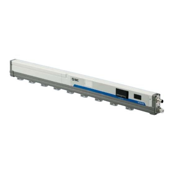
Summary of Contents for SMC Networks IZS51 Series
- Page 1 Doc.No.DOC1092338 PRODUCT NAME Ionizer Bar Type MODEL / Series / Product Number IZS51 series...
-
Page 2: Table Of Contents
Contents Safety Instructions ..............................3 Limitation of Use ................................. 5 Procedures to Operation ..........................10 1-1. Flow chart to operation for IZS51-□□N (NPN type), IZS51-□□P (PNP type) ......... 10 1-2. Flow chart to operation for IZS51-□□L (IO-Link type) ................11 Installation and Electrical Connection ...................... -
Page 3: Safety Instructions
Safety Instructions These safety instructions are intended to prevent hazardous situations and/or equipment damage. These instructions indicate the level of potential hazard with the labels of “Caution,” “Warning” or “Danger.” They are all important notes for safety and must be followed in addition to International Standards (ISO/IEC) , and other safety regulations. -
Page 4: Limited Warranty And Disclaimer/Compliance Requirements
Safety Instructions Caution We develop, design, and manufacture our products to be used for automatic control equipment, and provide them for peaceful use in manufacturing industries. Use in non-manufacturing industries is not covered. Products we manufacture and sell cannot be used for the purpose of transactions or certification specified in the Measurement Act. -
Page 5: Limitation Of Use
Limitation of Use Selection Warning 1) This product is intended for use in general factory automation equipment. · If considering using the product for other applications (especially those indicated in (4) on page 3), please consult SMC beforehand. 2) Use within the specified voltage and temperature range. ·... - Page 6 5) Tighten the screws to the specified torque. · If the screws are tightened in excess of the specified torque range, it may damage the mounting screws or mounted areas. · If the tightening torque is insufficient, the mounting screws and brackets may become loose. 6) Do not directly touch the emitters.
- Page 7 4) When the build-in sensor is on and cannot be adjusted ion balance to zero by pressing the button, turn the sensor off. · The sensor may malfunction if there is an object with too much charge around it. 5) Use specified brackets for fixing. ·...
-
Page 8: Maintenance / Check
l. Locations which are subject to potential lightning strikes. m. In an area where the product may receive direct impact or vibration. n. Areas where the product may be subjected to forces or weight that could cause physical deformation. 4) Ionizer, Remote controller and AC adapter are not resistant to lightening surge. Maintenance / Check Warning 1) Perform maintenance regularly and clean the emitters. - Page 9 Handling Caution 1) Do not apply excessive external force or shock (100m/s or more) to the product. · Even if the there are no problems with the appearance of the Ionizer, the damage of the internal components may cause malfunction. ·...
-
Page 10: Procedures To Operation
1. Procedures to Operation 1-1. Flow chart to operation for IZS51-□□N (NPN type), IZS51-□□P (PNP type) Start Installation of ionizer Refer to [2-1. Installation ]. Wiring of ionizer Refer to [2-2. Electrical connection ]. Piping of ionizer Air purge Refer to [2-1. Installation ]. Pressure setting Refer to [2-1-3. -
Page 11: Flow Chart To Operation For Izs51-□□L (Io-Link Type)
1-2. Flow chart to operation for IZS51-□□L (IO-Link type) Start Installation of ionizer Refer to [2-1. Installation ]. Wiring of ionizer Refer for [2-2. Electrical connection ]. Piping of ionizer Air purge Refer to [2-1. Installation ]. Pressure setting Refer to [2-1-3. Adjustment of Pressure (Flow adjustment) ] Turn ON power supply Set up IO-Link... -
Page 12: Installation And Electrical Connection
2. Installation and Electrical Connection · The performance of the product varies depending on the surrounding installation and operating conditions. It is recommended to investigate in advance any processes and parts where static electricity disturbances occur. Verify that the required conditions have been met in order to effectively remove static electricity before installation. -
Page 13: Adjustment Of Pressure (Flow Adjustment)
2-1-3. Adjustment of Pressure (Flow adjustment) · When air is supplied to the ionizer, adjust the flow using a regulator which should be connected immediately before the ionizer. If a flow adjustment valve is used between the ionizer and regulator, the speed of the flow from the nozzle decreases due to the pressure decrease, decreasing the neutralizing performance. -
Page 14: Installation Of Bracket
2-1-5. Installation of bracket · 2 types of end bracket and intermediate bracket are available. When end bracket 1 is used, use intermediate bracket 1. For end bracket 2, use intermediate bracket 2. 1) End bracket · Use specified end bracket. ·... -
Page 15: Electrical Connection
4) Mounting angle adjustment · Adjust the mounting angle of the product for effective neutralization, and fix the product with the rotating set screw. (M4) at each bracket. Tightening torque IZS51-BE1 (End bracket 1): 0.72 to 0.76Nm IZS51-BE2 (End bracket 2): 0.72 to 0.76Nm IZS51-BM1 (Intermediate bracket 1): 0.47 to 0.49Nm IZS51-BM2 (Intermediate bracket 2): 0.47 to 0.49Nm M4 screw... - Page 16 Table 3. Wiring table for power supply cable (IZS51-CP) Cable Signal Signal Description color direction Brown DC(+) Connect the power supply to operate the ionizer. Note) Signal input to stop ion generation Ion generation Pink NPN type: Ion generation is stopped by connecting to 0V. stop signal PNP type: Ion generation is stopped by connecting to 24VDC.
-
Page 17: Electrical Connection: Izs51-□□L (Io-Link Type)
PNP type Shield Ionizer PNP type Shield wire Make sure to ground with a resistant of 100 ohms or less. +24V Brown DC+) +DC24V Power supply DC/DC Blue DC(-) - F.G. Make sure to ground with a resistant of 100 ohms or less. OUTPUT INPUT Pink... - Page 18 [Relay cable IZS51-CF] · A cable for IO-Link communication with this product. · Connect the relay cable socket to power supply connector of the ionizer and connect the relay cable plug to the T-connector socket. · The connector key code A is used for the relay cable, power supply connector and the T-connector. Pay attention to the key alignment when connecting them.
-
Page 19: Connecting Of The Ac Adapter
2-2-5. Connecting of the AC adapter · Perform F.G. wiring with the ground terminal (F.G.) of the AC cord when AC adapter is used. If the AC cord is plugged in, plug it into a grounded outlets with less than 100Ω. Use an AC cord with ground terminal, if it is prepared by the user. -
Page 20: Timing Chart
2-4. Timing chart 2-4-1. Normal operation: when ion generation stop/air supply stop synchronization is ON Normal operation Air supply stop Ion generation stop signal (input → release) Ion generation stop Power ON/OFF External input Button input (key input) → Button input (key input) External input signal signal Ion generetion... - Page 21 Normal operation Ion generation stop signal Ion generation stop signal (input → release) (input→release) Button input (key input) → External input signal Power supply ON/OFF Ion generetion Ion generetion Ion generation Ion generetion Ion generation stop signal stop signal stop signal stop signal stop signal input...
-
Page 22: Normal Operation: When Ion Generation Stop/Air Supply Stop Synchronization Is Off
2-4-2. Normal operation: when ion generation stop/air supply stop synchronization is OFF Normal operation Air supply stop Ion generation stop signal (input → release) Ion generation stop Power ON/OFF External input Button input (key input) → Button input (key input) External input signal signal Ion generetion... - Page 23 Normal operation Ion generation stop signal Ion generation stop signal (input → release) (input→release) Button input (key input) → External input signal Power supply ON/OFF Ion generetion Ion generetion Ion generetion Ion generation Ion generation stop signal stop signal stop signal stop signal stop signal input...
-
Page 24: Setting Mode
2-4-3. Setting mode Setting mode Switching from Switching from normal operation Switch to next each setting mode Each setting mode mode various setting normal operation mode Ion generetion Ion generation stop signal [Button input] stop signal [Button input] Display Status Setting input release... -
Page 25: In Case Of Error Or Warning
2-4-4. In case of error or warning Output signal over current Abnormality of the power supply Abnormality of the CPU Abnormality of the high voltage "OC.E" (Error signal) Maintenance warining "PW.C" "CPU" "HV" "OC.M" (Maintenance signal) "NDL" "PW.I" "OC.C" (Condition signal) Display Status Power... -
Page 26: Setting
3. Setting 3-1. Operation mode · The product has 2 operation modes. AC mode or DC mode (Either positive ions or negative ions are continuously discharged during operation). 1) AC mode · Positive ions and negative ions are generated alternately according to the frequency set by the frequency set mode. -
Page 27: Remote Controller
3-2-2. Remote controller Applicable models: IZS51-□□N, IZS51-□□P · An infrared ray type remote controller is used for these models. Communication cannot be established if there are obstacles between the remote controller and ionizer. When operating with a remote controller, install the ionizer with the receiving part exposed, and point the sending part of the remote controller at the receiving part of the ionizer. -
Page 28: Setting Of The Ionizer
3-3. Setting of the Ionizer Default settings 3-3-1. When set by button operation Frequency setting: 100Hz Built-in sensor: ON Power is supplied Maintenance detection level: LOW Key lock: OFF [Normal operation] Press S button once Press the ▲ Press S button button and S for 4 seconds [Frequency set mode]... -
Page 29: When Set By Remote Controller Operation
3-3-2. When set by remote controller operation Power is supplied [Normal operation] Press ID key once [Select ID number] Input ID number of the Ionizer to be controlled by number key (0 to 15). Refer to [3-2-2. Remote controller] for details. Press SET key once Press END key once [Frequency set mode]... -
Page 30: Setting Mode
3-4. Setting mode 3-4-1. Frequency set mode · Set the ion generation frequency. [Ion generation frequency setting] “FRQ” flash (green) · Press the S button once in normal operation. The frequency display will change to “FRQ” flashing in green. · The Ion generation frequency is set by pressing the ▲ button or ▼ button. -
Page 31: Offset Voltage Adjustment Mode
3-4-2. Offset voltage adjustment mode · Offset voltage is adjusted before shipment. However, readjustment of the offset voltage is possible where it is required depending on the installation environment. (The same applies when the ionizer is moved and installed in a different location.) ·... -
Page 32: Balance Control Set Mode
3-4-3. Balance control set mode · This product has a built-in sensor to balance the ions generated. · Balance control set mode turns the balance control by the built-in sensor on and off. · The sensor may not operate correctly if an object with much charge comes too close to the sensor. In that case, please turn off the balance control. -
Page 33: Maintenance Detection Level Selection Mode
3-4-4. Maintenance detection level selection mode · If this product is used for an extended period of time, contamination such as dust will stick to the emitters, reducing the static neutralization performance. · The timing of when maintenance is required varies depending on the environment in which it is installed. ·... -
Page 34: Ion Generation Stop/Air Supply Stop Synchronization Set Mode
3-4-5. Ion generation stop/air supply stop synchronization set mode · Possible to stop air supply by closing build-in valve in using the model with valve unit. · Selects synchronization ON (which stops air supply synchronized with ion generation stop) or OFF (which stops air supply by external input signal rather than synchronizing with ion generation stop). -
Page 35: Id Number Setting Mode
3-4-6. ID number setting mode · Possible to set only transistor input/output type (IZS51-□□N, IZS51-□□P) can be operated remote controller. · Not possible to set IO-Link type (IZS51-□□L), ID number display is OFF. [ID number setting] “ID” flash (green) · Press the S button six times in normal operation. The frequency display will change to “ID”... -
Page 36: Ion Generation Stop Mode
3-4-7. Ion generation stop mode · In addition to the external input signal, the product will stop ion generation temporarily by pressing buttons. · If ion generation stop/air supply stop synchronization is ON in using the model with valve unit, stop air supply by closing build-in valve when input ion generation stop signal. -
Page 37: Restore To Factory Settings Mode
3-4-9. Restore to factory settings mode · Possible to restore each setting of Ionizer to factory settings. [How to restore to factory settings] “DEF” flash (red) After switching to [Output signals check mode] by pressing the ▲ button and S button simultaneously for 2s or longer in normal operation, press the S button once more. -
Page 38: Alarm Function
3-5. Alarm function · When a problem occurs, an output signal or LCD display notification is generated. Depending on the content of abnormality, this product either continues or stops operation. Table 9. Alarm list Operation of the How to return to work Alarm name Output signal ionizer... -
Page 39: Io-Link Communication
4) Maintenance warning · The maintenance signal is ON when contamination, abrasion or damage to the emitters is detected. “NDL” is displayed in frequency display flashing green to indicate that cleaning or replacement of emitter cartridges needs to be performed. ·... -
Page 40: Communication Date
4-3. Communication date [Service data] · The tables below indicate the parameters that can be read or written by a simple access parameter (Direct Parameter Page1) and ISDU parameters that are applicable to various parameters and commands. ●Direct Parameter Page1 DPP1 address Access Parameter... - Page 41 ●SystemCommand (Index2) · The commands shown in the table below can be issued in SystemCommand of ISDU Index 0x002. · The button of each system command is displayed on the IO-Link setting tool. · Click the button to send the system command to the product. ·...
- Page 42 ●Product original parameters Index Date Initial Data Note1) Access Parameter Value Description Note2) Note3) index type value storage (Decimal) 0x40 Displays the model Series 1: IZS51-L (64) information. Sets ON/OFF of the 0x41 0: Balance control is OFF Balance control balance control by (65) 1: Balance control is ON...
- Page 43 Data type Data length Symbol Description (IO-Link standard) Bit [byte] 8 [1] UIntegerT Unsigned integer 16 [2] [ProcessData] Process data is the data exchanged periodically between the master and device. The discharged state, ion balance, diagnosis information, and other data are configured in this product as shown in the table below.
-
Page 44: Alarm Function
Bit offset Process data Item Air supply Reserved Offset voltage adjustment output valid generation Bit offset Item Offset voltage adjustment The process data of this product is of Big endian type. When the transmission method of the upper communication is of Little endian type, the byte order will be changed. -
Page 45: Performance
5. Performance 5-1. Static Neutralization Characteristics · Performance data shown in this chapter is based on an electrified plate (dimensions: 150 x 150 mm, electrostatic capacity: 20pF) defined by ANSI standard (ANSI/ESD STM3.1-2015). Use this data as a guideline for selection, as the performance data may vary depending on the material and size of the workpiece. (1) Installation distance and Discharge time (Discharge time from 1000V to 100V) For cartridges without air purge Low flow cartridge... - Page 46 Low flow cartridge, Supply pressure:0.3MPa Middle flow cartridge, Supply pressure:0.3MPa High flow cartridge, Supply pressure:0.3MPa...
-
Page 47: Pressure - Flow Rate Characteristics
5-2. Pressure – Flow rate characteristics [Without valve unit] IZS51-□□T(C) IZS51-□□J(K) IZS51-□□V(S) High flow cartridge Middle flow cartridge Low flow cartridge Bar length Bar length 1000 symbol Bar length symbol symbol Pressure [MPa] Pressure [MPa] Pressure [MPa] [With valve unit] IZS51-□□V(S) IZS51-□□T(C) IZS51-□□J(K) -
Page 48: How To Order
6. How to order 6-1. Ionizer Transistor IZS51 - Input/Output IZS51 - IO-Link (10) (11) (1) Bar length (4) Piping (7) Communication cable (For IO-Link type) Symbol Bar length (mm) Symbol Bar length (mm) Symbol Type Symbol Length 1100 With piping on both sides None Note 1) 1280... - Page 49 Made to order X10: Non-standard bar length Transistor IZS51 - - X10 Input/Output IZS51 - - X10 IO-Link Same as standard product (1) Bar length Length Length Length Length Length Symbol Symbol Symbol Symbol Symbol (mm) (mm) (mm) (mm) (mm) 1400 1760 2120...
-
Page 50: Accessories And Separately Ordered Item
6-2. Accessories and Separately ordered item Emitter cartridge IZS51 - N Nozzle Symbol Cartridge type Emitter material Nozzle color Cartridge color Tungsten White High flow cartridge Blue Silicon Gray Tungsten White Middle flow cartridge Gray Silicon Gray Emitter cartridge Tungsten White Low flow cartridge Black... - Page 51 Power supply cable (For NPN/PNP type) IZS51 - C P Symbol Length Power supply cable (For IO-Link type) IZS51 - C Q Symbol Length 0.5m Communication cable (For IO-Link type) IZS51 - C E Symbol Length 0.5m Relay cable (For IO-Link type) IZS51 - C Symbol Length...
-
Page 52: Remote Controller
T-connector IZS51 - C Remote controller IZS51 - R Drop prevention cover IZS51 - E Symbol Number of fixed emitter cartridges 3 pcs. 4 pcs. 5 pcs. Number of required drop prevention covers Standard bar length Non-standard bar length Number of required drop prevention covers Number of required drop prevention covers Symbol Symbol... - Page 53 Made to order Power supply cable (For NPN/PNP type) IZS51 - C P - X13 Symbol Length Relay cable (For IO-Link type) IZS51 - C - X13 Symbol Length Not included T-connector...
-
Page 54: Outline Dimensions
7. Outline dimensions Ionizer: IZS51-350 Ionizer: IZS51-380 to 2480 Ionizer with valve unit: IZS51-V Note) Applicable tube O.D. A (mm) Product No. n (pc.) L (mm) IZS51-35 φ4 IZS51-38 φ6 Metric IZS51-44 φ8 IZS51-56 φ10 IZS51-62 φ3/16” IZS51-80 φ1/4” Inch IZS51-110 1100 φ5/16”... - Page 55 End bracket: IZS51-BE1 Intermediate bracket: IZS51-BM1 Hexagon socket head cap screw (M4x8) (Including 4pcs.) Angle adjustable (+/-90 End bracket: IZS51-BE2 Intermediate bracket: IZS51-BM2 Hexagon socket head cap screw (M4x8) (Including 4pcs.) Angle adjustable (+/-10...
- Page 56 Power supply cable: IZS51-CP Shield Semi-stripped terminal Power supply cable Length: L Cable specifications Product No. L(mm) Number of poles 7 and shield wire IZS51-CP03 3000 Conductor Size AWG20 (2 pcs.), AWG28 (5 pcs.) IZS51-CP05 5000 Nominal cross section 0.54mm (2pcs.), 0.09mm (5pcs.) IZS51-CP10...
- Page 57 Relay cable (For IO-Link type): IZS51-CF M12 plug connector M12 socket connector (A-coded) (A-coded) Relay cable length: L Cable specifications Product No. L (mm) Number of poles 7 and shield wire IZS51-CF03 3000 Conductor Size AWG20 (2 pcs.), AWG28 (5 pcs.) IZS51-CF05 5000 Nominal cross section...
-
Page 58: Specifications
8. Specifications Ionizer Ionizer model IZS51-□□N (NPN type) IZS51-□□P (PNP type) IZS51-□□L (IO-Link type) Ion generation method Corona discharge method Note1) Method of applying voltage AC, DC Note2) Applied voltage +/-7,000V Note3) Offset voltage Within +/-30V Fluid Air (Clean and dry) Operating 0.5MPa or less pressure... - Page 59 Communication specification of IO-Link IO-Linik type Device IO-Linik version V1.1 Configuration file format IODD file Communication speed COM2(38.4kbps) Minimum cycle time 8.0ms Process data length INPUT Data:3byte、Output Data:2byte On-Request data Compatible Data storage Compatible Event Compatible Vender ID 131(0×0083) Device ID 666(0×00029A) Emitter cartridge qty., weight Symbol for bar length...
-
Page 60: Troubleshooting
Troubleshooting... -
Page 62: Maintenance
9. Maintenance Warning · A high voltage generating circuit is mounted onto this product. · Verify that the power supply is OFF when performing maintenance. · Never disassemble or modify the product, as this can cause loss of product functionality and a risk of electric shock and earth leakage. - Page 63 Cleaning procedure by using IZT43-M2 a. Before cleaning the emitters, shutoff the power and air supply. b. The emitters may be cleaned with the emitter cartridges mounted to the Ionizer body or with the cartridges removed from the Ionizer body. Refer to the figure on the right for instructions on how to remove the cartridges.
- Page 64 Revision history Tel: + 81 3 5207 8249 Fax: +81 3 5298 5362 https://www.smcworld.com Note: Specifications are subject to change without prior notice and any obligation on the part of the manufacturer. © SMC Corporation All Rights Reserved...
Need help?
Do you have a question about the IZS51 Series and is the answer not in the manual?
Questions and answers