Advertisement
Quick Links
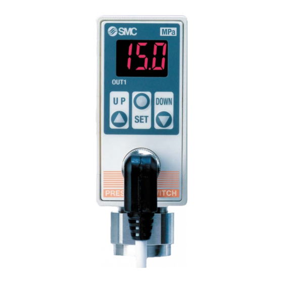
2-Colour Display Digital Pressure Switch
NPN/PNP open collector 2 outputs added.
Cut-to-zero display function added.
For
For
For
10
10
General
General
General
Fluids
Fluids
Fluids
(ISE75)
1
1
For Air
For Air
For Air
(ISE70)
2-Colour Display (Green/Red)
•
Selectable from four patterns
ON
q
Red
w
Green
e
Red
r
Green
Easily identifiable abnormal readings
Easily identifiable abnormal readings
10 mm character height
M12 Connector
•
Lead wire with M12 connector (5 m)
•
Straight and right-angled connectors
With Bracket
•
User-selectable mounting orientation
• Withstand pressure: Rated pressure x 3
• Withstand pressure: Rated pressure x 3
• Model with initial display settings of PSI is also available as standard.
• Model with initial display settings of PSI is also available as standard.
• Port size
• Port size
Rc1/4, NPT1/4, G1/4 (ISO1179)
Rc1/4, NPT1/4, G1/4 (ISO1179)
Rc1/4, NPT1/4, G1/4 (ISO1179)
ISE70/75/75H
Series
Rated Pressure
Rated Pressure
Rated Pressure
15
15
MPa
MPa
•
•
MPa
MPa
2-colour
2-colour
digital
digital
digital
OFF
Green
Red
Red
Green
Functions
• Anti-chattering
• Zero-out
• Unit display switching
(Fixed SI unit in Japan)
MPa
MPa
(ISE75H)
IP67
IP67
• Display calibration
• Key lock
For Air
ISE70
ISE75
(
)
1 MPa
MPa
OUT1
OUT1
U P
DOWN
U P
SET
Plain
PRESSURE SWITCH
PRESSURE SWITCH
∗ The ISE70/75 series has been remodelled.
For General Fluids
ISE75H
(
)
10 MPa
MPa
OUT1
DOWN
U P
SET
SET
Grey
PRESSURE SWITCH
CAT.EUS100-52C-UK
®
(
)
15 MPa
MPa
DOWN
Orange
Advertisement

Related Manuals for SMC Networks ISE70 Series


Summary of Contents for SMC Networks ISE70 Series
- Page 1 2-Colour Display Digital Pressure Switch ® NPN/PNP open collector 2 outputs added. Cut-to-zero display function added. ∗ The ISE70/75 series has been remodelled. Rated Pressure Rated Pressure Rated Pressure General General General • • Fluids Fluids Fluids (ISE75) (ISE75H) For Air For Air For Air 2-colour...
-
Page 2: How To Order
2-Colour Display Digital Pressure Switch For Air ISE70 Series ® ∗ The ISE70 series has been remodeled. Click here for details. How to Order ISE70 1 MPa Piping Rc1/4 NPT1/4 G1/4 (ISO1179) Option 2 None — Output With bracket 2 settings NPN open collector 2 outputs ((Pin no.: 2, 4) - Page 3 ISE70 2-Colour Display Digital Pressure Switch Series For Air Specifications ISE70 Model Rated pressure range 0 to 1 MPa Set pressure range –0.1 to 1 MPa Withstand pressure 1.5 MPa 0.01 MPa Set pressure resolution Air, Non-corrosive gas, Non-flammable gas Applicable fluid 12 to 24 VDC±10%, Ripple (p-p) 10% or less (with power supply polarity protection) Power supply voltage...
- Page 4 2-Colour Display Digital Pressure Switch For General Fluids ISE75/75H Series ® ∗ The ISE75 (For 10 MPa) series has been remodelled. Click here for details. How to Order 43 M ISE75 10 MPa ISE75H 15 MPa Piping Rc1/4 NPT1/4 Option 2 G1/4 (ISO1179) None —...
- Page 5 ISE75/75H 2-Colour Display Digital Pressure Switch Series For General Fluids Specifications ISE75 ISE75H Model Rated pressure range 0 to 10 MPa 0 to 15 MPa Set pressure range 0.4 to 10 MPa 0.5 to 15 MPa Withstand pressure 30 MPa 45 MPa Set pressure resolution 0.1 MPa...
- Page 6 ISE70/75/75H Series Descriptions Indication light (Green) Displays the switch operation status. Displays the current pressure condi- Lights up when OUT1 is turned ON. tion, set mode and error code. The display mode can be selected from four options: fixed green single-co- SET button OUT1 OUT2...
- Page 7 2-Colour Display Digital Pressure Switch ISE75/75H Series For General Fluids Functions Display calibration function Error function This function eliminates slight differences in the output values and Take the following corrective solutions when error occurs. allows uniformity in the numbers displayed. Displayed values of the Error pressure sensor can be calibrated to within ±5% of their readings.
- Page 8 ISE70/75/75H Series Dimensions „24 ISE70/75/75H Piping port 02: Rc1/4 N02: NPT1/4 F02: G1/4 (ISO1179) OUT1 DOWN PRESSURE SWITCH Note) The connector faces down (toward the piping). Do not attempt to rotate the con- nector, as it is not rotatable. Color (31) 15.7 (38.7)
-
Page 9: Safety Instructions
Safety Instructions These safety instructions are intended to prevent hazardous situations and/or equipment damage. These instructions indicate the level of potential hazard with the labels of “Caution,” “Warning” or “Danger.” They are all important notes for safety and must be followed in addition to International ∗1) ∗2) Standards (ISO/IEC), Japan Industrial Standards (JIS) - Page 10 When connecting the pipe to the switch, apply a torque of 13.6 N·m or greater for the ISE70 series and a torque of 25 2. Connections should be done while the power N·m or greater for the ISE75/75H series.
- Page 11 ISE70/75/75H Series Specific Product Precautions 2 Be sure to read this before handling. Refer to back page 1 for Safety Instructions and “Precautions for Handling Pneumatic Devices” (M-03-E3A) for Pressure Switches Precautions. Set Pressure Range and Rated Pressure Range Caution 1.
-
Page 12: Limited Warranty And Disclaimer/ Compliance Requirements
These safety instructions are intended to prevent hazardous situations and/or equipment Safety Instructions damage. These instructions indicate the level of potential hazard with the labels of “Caution,” “Warning” or “Danger.” They are all important notes for safety and must be followed in addition to International Standards (ISO/IEC) 1) , and other safety regulations. - Page 13 SMC Corporation (Europe) +43 (0)2262622800 www.smc.at offi ce@smc.at +370 5 2308118 www.smclt.lt info@smclt.lt Austria Lithuania +32 (0)33551464 www.smc.be info@smc.be Netherlands +31 (0)205318888 www.smc.nl info@smc.nl Belgium +359 (0)2807670 www.smc.bg offi ce@smc.bg +47 67129020 www.smc-norge.no post@smc-norge.no Bulgaria Norway Croatia +385 (0)13707288 www.smc.hr offi...
Need help?
Do you have a question about the ISE70 Series and is the answer not in the manual?
Questions and answers